Map interface, Map interface –12 – Altera CPRI IP Core User Manual
Page 44
4–12
Chapter 4: Functional Description
MAP Interface
CPRI MegaCore Function
December 2013
Altera Corporation
User Guide
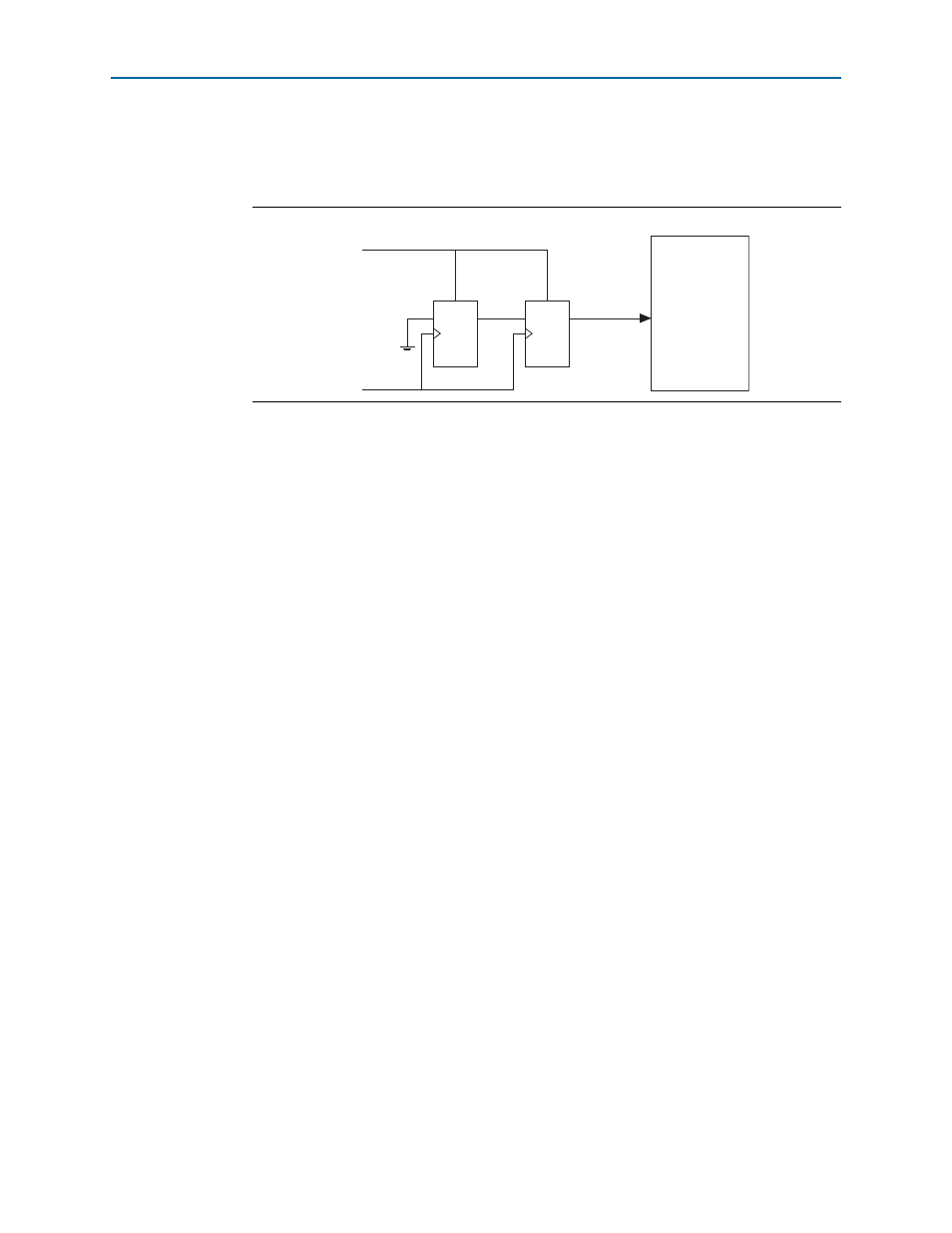
You must implement logic to ensure the minimal hold time and synchronous
deassertion of each reset input signal to the CPRI IP core.
shows a circuit
that ensures these conditions for one reset signal.
For more information about the requirements for reset signals, refer to
The CPRI IP core has a dedicated reset control module to enforce the specific reset
requirements of the high-speed transceiver module. This reset controller generates the
recommended reset sequence for the transceiver. The
reset
signal controls the reset
control module.
In Arria V, Cyclone V, and Stratix V devices, the Altera Deterministic Latency PHY IP
core or Altera Native PHY IP core that is generated with the CPRI IP core implements
the reset controller. In earlier device families, the reset control module is internal to
the CPRI IP core, but external to the ALTGX megafunction instance generated with
the CPRI IP core.
After reset, your software must perform link synchronization and other initialization
tasks. For information about the required initialization sequence following CPRI IP
core reset, refer to
Appendix A, Initialization Sequence
MAP Interface
The CPRI IP core MAP interface comprises the individual antenna-carrier interfaces,
or data channels, through which the CPRI IP core transfers IQ sample data to and
from the RF implementation. The MAP interface is implemented as an incoming and
an outgoing Avalon-ST interface. The Avalon-ST interface provides a standard,
flexible, and modular protocol for data transfers from a source interface to a sink
interface.
f
For information about the Avalon-ST interface, refer to
Figure 4–6. Circuit to Ensure Synchronous Deassertion of Reset Signal
D
D
Q
Q
rst
rst
clk
rst
reset
CPRI
MegaCore
Function