Table 7–40 – Altera CPRI IP Core User Manual
Page 136
7–20
Chapter 7: Software Interface
MAP Interface and AUX Interface Configuration Registers
CPRI MegaCore Function
December 2013
Altera Corporation
User Guide
start_rx_offset_x
[7:0]
RW
Basic frame number for start of
cpri_rx_start
synchronization output.
8’h0
Notes to
:
(1) In synchronous buffer mode, the offset specified in this register must follow (be greater than) the offset specified in the
CPRI_MAP_OFFSET_RX
register described in
. For an explanation of this requirement and an overview of the considerations in determining the value in this
register, refer to
“MAP Receiver in Synchronous Buffer Mode” on page 4–21
and to
. If your register values do not
comply with this requirement, your CPRI IP core will experience data corruption on the active data channels in the synchronous buffer
synchronization mode.
(2) This register does not participate in data transfer synchronization on the antenna-carrier interfaces in FIFO mode or in the internally-clocked
mode.
Table 7–39. CPRI_START_OFFSET_RX—Rx Start Frame Offset
(1)
,
(2)
—Offset: 0x120 (Part 2 of 2)
Field
Bits
Access
Function
Default
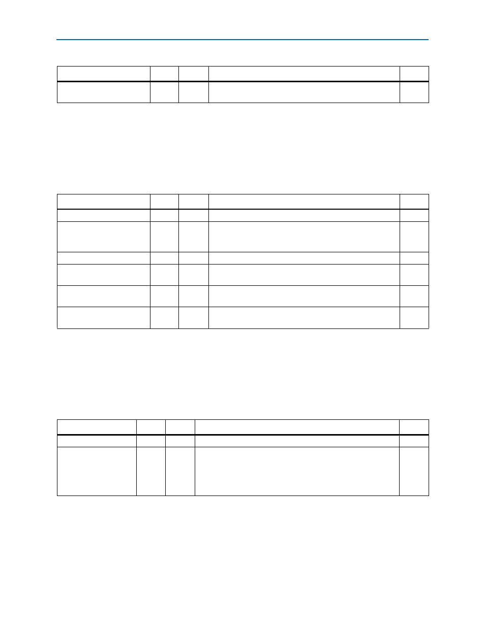
Table 7–40. CPRI_START_OFFSET_TX—Tx Start Frame Offset
—Offset: 0x124
Field
Bits
Access
Function
Default
RSRV
[31:25] UR0
Reserved.
7'h0
start_tx_hf_resync
[24]
RW
Enables synchronization every hyperframe instead of every
radio frame. When asserted, the
start_tx_offset_z
field is
ignored.
1’h0
RSRV
[23:22] UR0
Reserved.
2'h0
start_tx_offset_seq
[21:16] RW
Sequence number for start of
cpri_tx_start
synchronization output.
6’h0
start_tx_offset_z
[15:8]
RW
Hyperframe number for start of
cpri_tx_start
synchronization output.
8’h0
start_tx_offset_x
[7:0]
RW
Basic frame number for start of
cpri_tx_start
synchronization output.
8’h0
Notes to
:
(1) In synchronous buffer mode, the offset specified in this register must precede (be less than) the offset specified in the
CPRI_MAP_OFFSET_TX
register described in
. For an explanation of this requirement and an overview of the considerations in determining the value in this
register, refer to
“MAP Transmitter in Synchronous Buffer Mode” on page 4–27
. If your register values do
not comply with this requirement, your CPRI IP core will experience data corruption on the active data channels in the synchronous buffer
synchronization mode.
(2) This register does not participate in data transfer synchronization on the antenna-carrier interfaces in FIFO mode or in the internally-clocked
mode.
Table 7–41. CPRI_MAP_RX_READY_THR—CPRI Mapping Rx Ready Threshold—Offset: 0x128
Field
Bits
Access
Function
Default
RSRV
[31:4]
UR0
Reserved.
28’h0
map_rx_ready_thr
[3:0]
RW
Threshold for assertion of the
mapN_rx_valid
signal in FIFO
mode, for all data channels
N
. The
mapN_rx_valid
signal is
asserted only when the MAP Rx buffer for data channel
N
fills
beyond this threshold value. All the MAP Rx buffers have the same
depth, 16.
4’h8