Clock diagrams for the cpri ip core, Clock diagrams for the cpri ip core –5, Clocking diagrams in – Altera CPRI IP Core User Manual
Page 37: Clock
Chapter 4: Functional Description
4–5
Clocking Structure
December 2013
Altera Corporation
CPRI MegaCore Function
User Guide
Clock Diagrams for the CPRI IP Core
show the clocking schemes for CPRI IP cores configured as
RE slaves, RE masters, and REC masters that do not target an Arria V GT device or
that are not configured with a CPRI line rate of 9830.4 Mbps.
show the clocking schemes for
CPRI IP cores configured as RE slaves, RE masters, and REC masters with a CPRI line
rate of 9830.4 Mbps that target an Arria V GT device. These variations have no clock
divider and no Tx elastic buffer or Rx elastic buffer. However, they require two
additional synchronized input clocks,
usr_pma_clk and usr_clk.
You must drive the usr_pma_clk and usr_clk clocks at the , which you must drive at
the frequency of 122.88 MHz, and
usr_clk,
which you must drive at the frequency of
245.76 MHz.
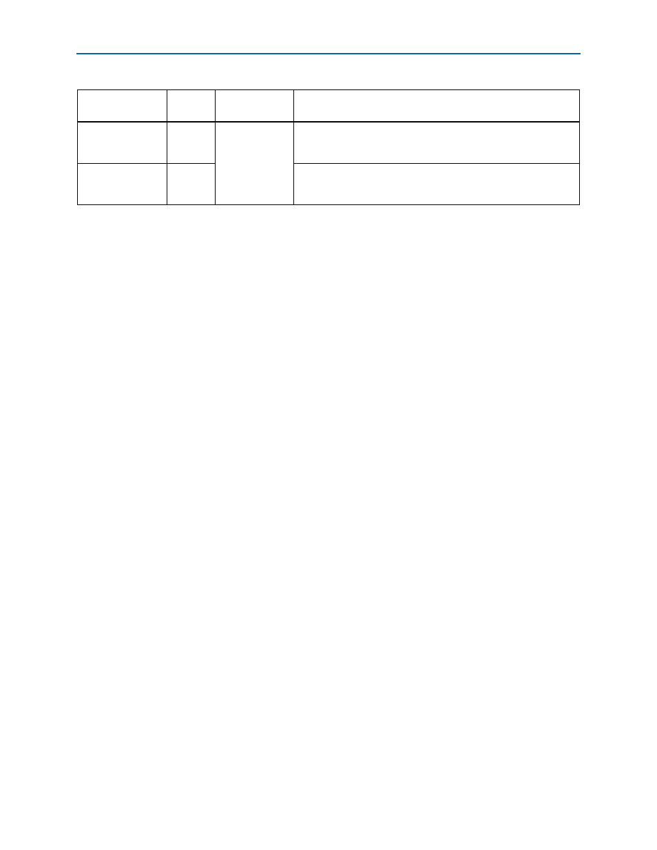
usr_pma_clk
Input
Present in
variations
configured at
9830.4 Gbps that
target an
Arria V GT device
Extra clock signal required to drive the PMA in these CPRI IP core
variations. Refer to
for driver frequency and
synchronization requirements.
usr_clk
Input
Extra clock signal required to drive the PCS in these CPRI IP core
variations. Refer to
for driver frequency and
synchronization requirements.
Table 4–1. CPRI IP Core Clocks (Part 3 of 3)
Clock Name
Direction
Configuration
Requirements
Description