Map receiver in fifo mode, Map receiver in fifo mode –20, Fifo mode – Altera CPRI IP Core User Manual
Page 52
4–20
Chapter 4: Functional Description
MAP Interface
CPRI MegaCore Function
December 2013
Altera Corporation
User Guide
For descriptions of the signals in
, refer to
and to the
following sections.
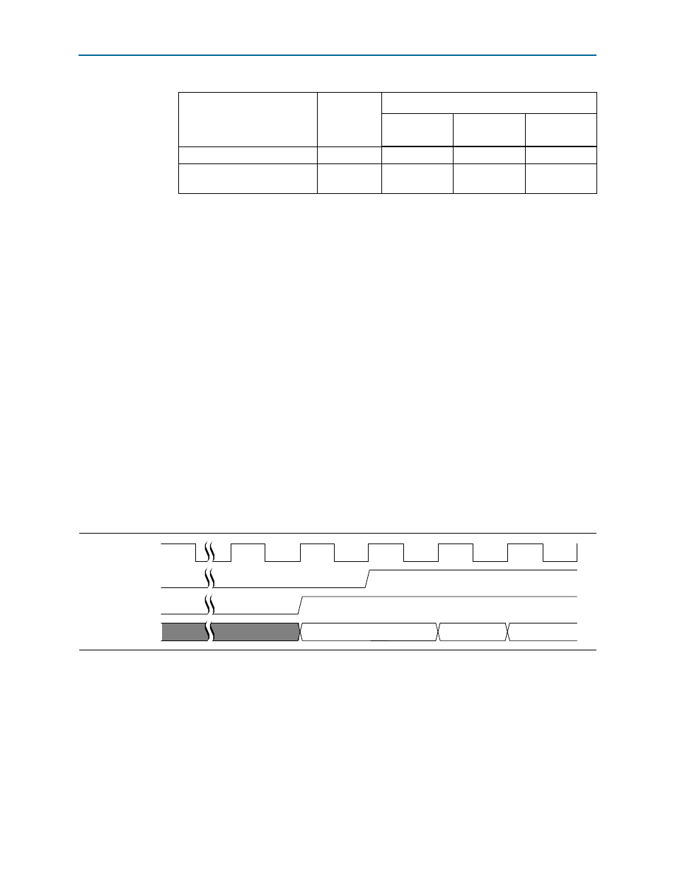
MAP Receiver in FIFO Mode
In FIFO mode, each data channel, or AxC interface, is clocked by an
application-driven clock
mapN_rx_clk
, and has an output data-available signal,
mapN_rx_valid
. Each AxC interface
N
asserts its
mapN_rx_valid
signal when it has
data available to send on this data channel—when the buffer level is above the
threshold indicated in the
CPRI_MAP_RX_READY_THR
register.
For details about the behavior of the individual signals in FIFO mode, refer to
shows the typical behavior of the MAP Rx
signals in this synchronization mode.
When the application is ready to receive data on the data channel, it asserts the
mapN_rx_ready
signal. While the CPRI IP core asserts the
mapN_rx_valid
signal and
the
mapN_rx_ready
signal is not asserted, the CPRI IP core holds the data value on
mapN_rx_data[31:0]
. The application must assert the
mapN_rx_ready
signal before the
mapN Rx buffer overflows, to avoid data corruption. While the
mapN_rx_ready
signal
map{23…0}_rx_start
Output
—
v
map{23…0}_rx_status_data
[2:0]
Output
v
v
v
Notes to
(1) A checkmark indicates the signal is used in a synchronization mode, and a dash indicates the signal is not used in
that synchronization mode.
(2) An entry with a dash indicates a signal that does not participate in the MAP receiver interface communication in
this synchronization mode. The signal is either not present in the configuration or is ignored. An input signal that
is ignored is ignored by the CPRI IP core. An output signal that is ignored should be ignored by the application.
Refer to
for information about the case that is relevant for each signal.
(3) A zero or one indicates the application must hold this input signal low or high, respectively.
(4) Altera recommends that you tie the
mapN_rx_ready
signals high or low in your internally-clocked variation, rather
than leave them floating.
Table 4–9. MAP Receiver Interface Signals by Synchronization Mode
(1)
(Part 2 of 2)
Signal Name
Direction
Available in Synchronization Mode
FIFO
Synchronous
Buffer
Internally
Clocked
Figure 4–9. MAP Receiver Interface in FIFO Mode
mapN_rx_clk
mapN_rx_ready
mapN_rx_valid
mapN_rx_data[31:0]