Overview, Installing the controller, Overview -2 installing the controller -2 – Rockwell Automation DAG6.5.8 APPLICATION GUIDE SCADA SYSTEM User Manual
Page 70
Publication AG-UM008C-EN-P - February 2005
3-2 Configuring MicroLogix 1100/1200/1500 Controllers
Overview
To configure a MicroLogix 1100/1200/1500 controller:
1. Install the controller; connect the serial cable to one of the
communication channels.
2. Define the processor’s communication characteristics using
RSLogix
™
500 programming software.
3. Install and configure the modem for communication with the
controller; connect the modem to one of the controller’s serial
channels.
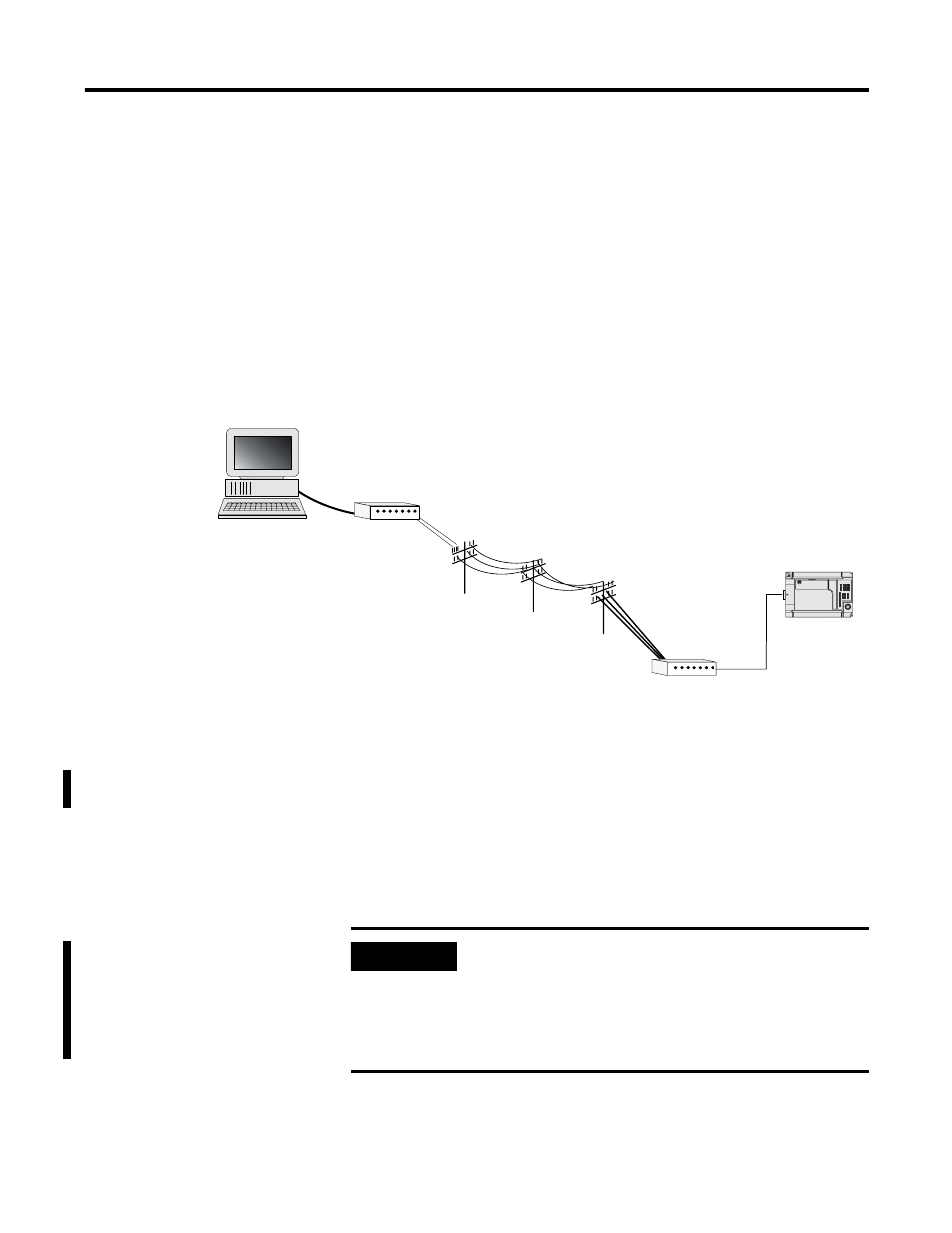
Figure 3.1 Configuring a MicroLogix 1100/1200/1500 Controller
Installing the Controller
For details about installing the controller, see the MicroLogix 1100
Installation Instructions, publication 1763-IN001, MicroLogix 1200
Installation Instructions, publication 1762-IN006 or the MicroLogix
1500 Installation Instructions, publication 1764-IN001. Cable pinouts
are shown in each example configuration as well as in Appendix A.
RSLogix 500 Programming Software
Modem
Modem
MicroLogix 1500
IMPORTANT
The MicroLogix 1200/1500 channel 0 port is not
optically isolated. For all modem applications, an
external optical isolator is recommended. You may
either supply your own or use a 1761-NET-AIC. The
MicroLogix 1500 Channel 1 port and MicroLogix
Channel 0 port are optically isolated.