Rockwell Automation DAG6.5.8 APPLICATION GUIDE SCADA SYSTEM User Manual
Page 172
Publication AG-UM008C-EN-P - February 2005
4-34 Configuring SLC 5/03, 5/04, and 5/05 Processors
Use Worksheet 4.4 (page D-17) for an example configuration and to
record your station’s configuration.
Define the communication parameters shown in Table 4.9 when
configuring an SLC 5/03, 5/04, or 5/05 processor for DF1 full-duplex
communication.
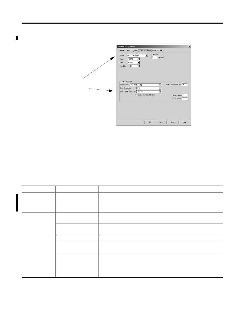
3. On the Channel 0 tab, choose
DF1 Full-Duplex for your
Driver.
4. Configure the communication
driver characteristics
according to Table 4.9.
Table 4.9 Configure an SLC 5/03, 5/04, or 5/05 Processor for DF1 Full-Duplex Communication
Tab
Parameter
Selections
General
Diagnostic File
SLC 5/03 (OS 302 C or higher), 5/04 (OS 401 C or higher) and 5/05 only. Select an
unused file (9 to 255) to store channel status information. You must define a
diagnostic file in order to be able to view channel 0 status. See See Table 4.10 on
page 4-36 for a file description.
Chan. 0 System
Baud Rate
Select a communication rate that all devices in your system support. Configure all
devices in the system for the same communication rate.
Parity
Parity provides additional message packet error detection. To implement even parity
checking, choose Even. To implement no parity checking, choose None.
Stop Bits
Match the number of stop bits to the devices with which you are communicating.
Source ID
This is the address, in decimal, that is used as the source address in any message
initiated by this processor.
Control Line
This parameter defines the mode in which the driver operates. Choose a method
appropriate for your system’s configuration:
•
If you are not using a modem, choose NO HANDSHAKING.
•
If you are using full-duplex modems, choose FULL-DUPLEX MODEM.
See page 4-5 for descriptions of the control line operation settings.