Rockwell Automation DAG6.5.8 APPLICATION GUIDE SCADA SYSTEM User Manual
Page 249
Publication AG-UM008C-EN-P - February 2005
Configuring Logix Controllers 7-23
Use Table 7.8 to help you understand the screen parameters you need
to specify on the Controller Properties screen.
Use Worksheet 7.4 (page D-25) for an example configuration and to
record your station’s configuration.
Table 7.8 Configuring a Logix controller for DF1 full-duplex communication
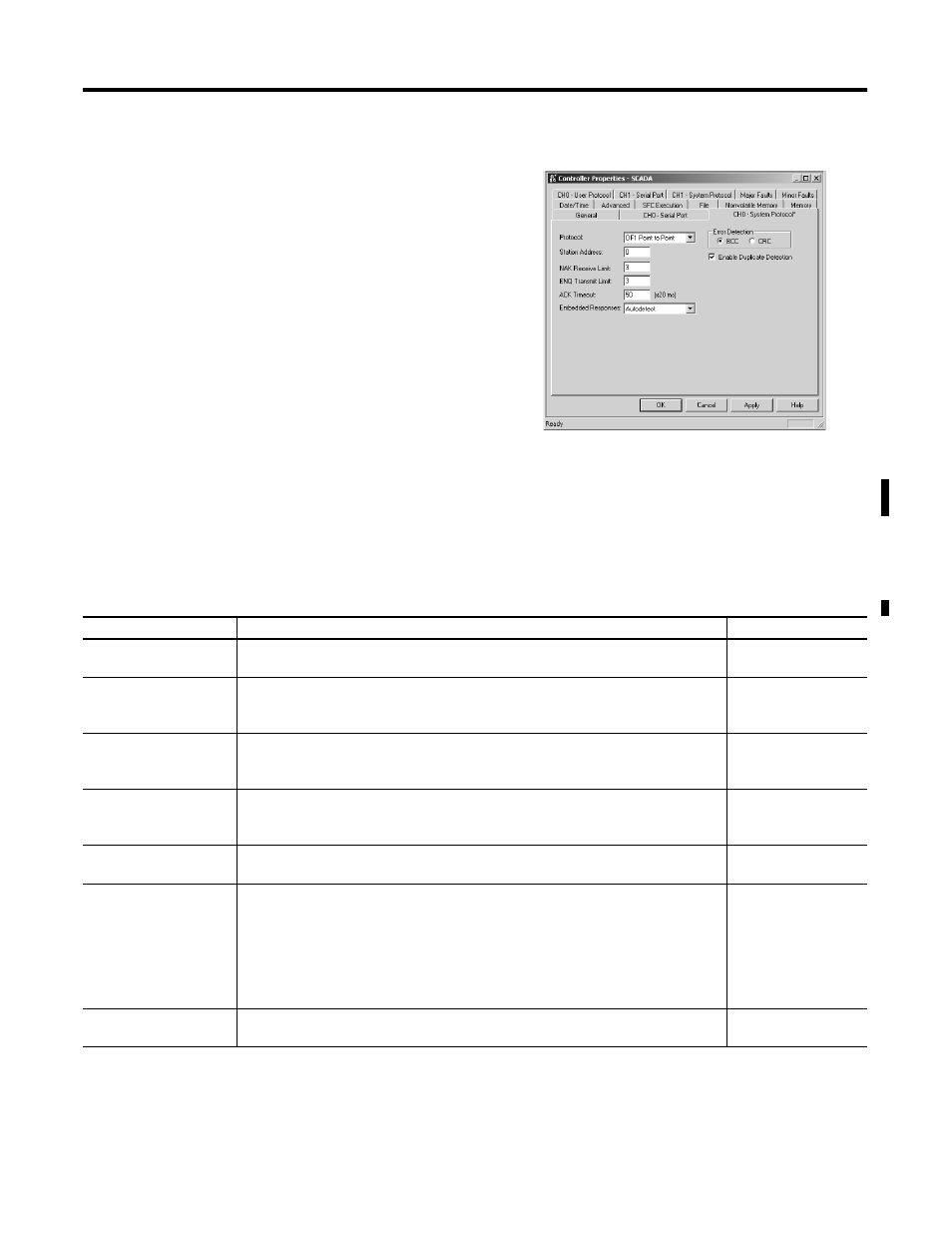
2. Choose the Serial Port Protocol tab
and configure according to your
specification. Serial Port Protocol
parameters and defaults can be
found in Table 7.8.
Parameter
Description
Default
Station Address
The station address for the serial port on the DF1 point-to-point network. Enter a valid
DF1 address (0 to 254).
0
NAK Receive Limit
Specifies the number of NAKs the controller can receive in response to a message
transmission.
Enter a value 0 to 127.
3
ENQ Transmit Limit
Specifies the number of inquiries (ENQs) you want the controller to send after an ACK
timeout.
Enter a value 0 to 127.
3
ACK Timeout
Specifies the amount of time you want the controller to wait for an acknowledgment
to its message transmission.
Enter a value 0 to 32767. Limits are defined in 20 ms intervals.
50 (1000 ms)
Embedded Response
Specifies how to enable embedded responses.
Select Autodetect (enabled only after receiving one embedded response) or Enabled.
Autodetect
Error Detection
Select BCC or CRC error detection.
Configure all stations to use the same type of error checking.
BCC: the controller sends and accepts messages that end with a BCC byte for error
checking. BCC is quicker and easier to implement, but does not detect as many errors
as CRC.
CRC: the controller sends and accepts messages with a 2-byte CRC for error checking.
CRC is a more effective error detection algorithm.
BCC
Enable Duplicate
Detection
Select whether or not the controller should detect and ignore duplicate messages.
Enabled