Processor-to-processor, Considerations when configuring msg control blocks – Rockwell Automation DAG6.5.8 APPLICATION GUIDE SCADA SYSTEM User Manual
Page 198
Publication AG-UM008C-EN-P - February 2005
5-12 Configuring SLC 500 Processors with 1747-KE Interface Modules
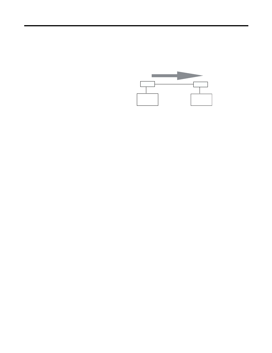
Processor-to-Processor
An SLC 5/02 processor can send messages to another processor in a
point-to-point configuration.
Considerations When Configuring MSG Control Blocks
Keep these considerations in mind when configuring messages
between an SLC 5/02 processor and a PLC-5 processor.
Point-to-Multipoint and Point-to-Point Link Configurations
•
In the SLC 5/02 MSG instruction, Target Node is the decimal
DH-485 node address of the 1747-KE module and Target Offset
is the decimal byte-offset, which is the element you want to
write data into or read data from.
•
The SLC 5/02 processor uses word addressing, while the PLC-5
processor uses byte addressing. In the Target Offset field of the
SLC 500 MSG control block, enter a word value equivalent to the
byte (element) of the PLC-5 file number you want to write data
into or read data from. For example in Figure 5.7, the Target
Offset is 20; this corresponds to element 10
10
in a PLC-5
processor because one word
=
two bytes. Never enter an odd
value for a Target Offset.
•
If you are sending messages between an SLC 5/02 processor and
a PLC-5 processor, then set S:2/8 in the SLC 5/02 status file to 1.
This bit is the CIF (Common Interface File) Addressing Mode
selection bit and lets the SLC 5/02 processor accept byte-offsets
from a PLC-5 processor.
•
The SLC 5/02 processor can only directly address words
0
10
-127
10
in a PLC-5 data table file. By specifying a byte-offset of
254 in the Target Offset field and specifying a Message Length of
41, you can indirectly address words 128
10
-167
10
in a PLC-5 data
table file. The maximum read or write message length for an
SLC 5/02 processor is 41 elements.
Station 1
Station 2
MSG
Modem
Modem