Figure 5.3 configuring the df1 port, Configure port as shown here – Rockwell Automation DAG6.5.8 APPLICATION GUIDE SCADA SYSTEM User Manual
Page 191
Publication AG-UM008C-EN-P - February 2005
Configuring SLC 500 Processors with 1747-KE Interface Modules 5-5
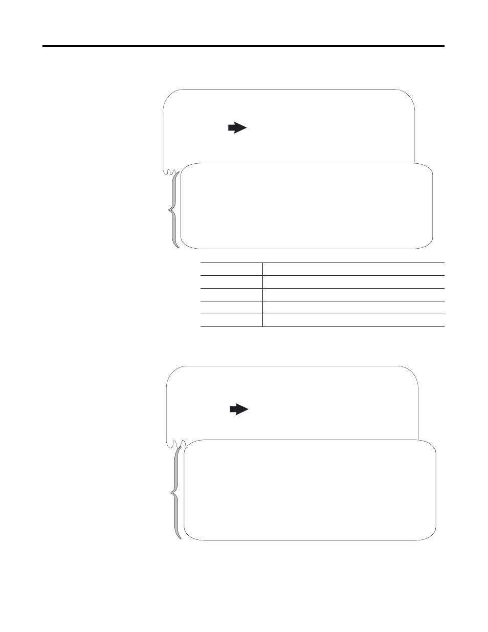
Figure 5.3 Configuring the DF1 Port
5. Configure the DH-485 port as shown in Figure 5.4.
Figure 5.4 Configuring the DH-485 Port
1747-KE Module, FRN# 4
Top Level Setup Menu.
1. CONFIG PORT
2. DF1 PORT
3. DH-485 PORT
4. DF1 PROTOCOL
5. DISPLAY PARAMETERS
X. SAVE AND EXIT
Enter Selection.....
DF1 PORT Setup Menu
1. Baud rate
2. Bits per character
3. Parity
4. Stop bits
X. SAVE AND EXIT
Enter Selection..... Baud Rate = 9600, New Value = 1200
Enter Selection.....Bits/Character = 8, New Value (7/8) = 8
Enter Selection..... Parity = N, New Value (E/O/N) = N
Enter Selection.....Stop Bits = 1, New Value (1/2) = 1
Configure the port as shown
here.
(These settings must match
those of the modem to which
you are connecting.)
Parameter
Selections
Baud rate
rate at which the device communicates
Bits per character
the number of bits that make-up a character
Parity
provides additional message packet error detection
Stop bits
delineates data during transfer
1747-KE Module, FRN# 3
Top Level Setup Menu.
1. CONFIG PORT
2. DF1 PORT
3. DH-485 PORT
4. DF1 PROTOCOL
5. DISPLAY PARAMETERS
X. SAVE AND EXIT
Enter Selection.....
DH-485 Setup Menu
1. Node Address
2. Maximum Node Address
3. Message Timeout
4. Pass Through
5. Baud rate
X. SAVE AND EXIT
Enter Selection.....DH-485 Node Address = 2, New Value (0-31) = 3
Enter Selection.....DH-485 Max Node Address = 31, New Value (1-31) = 31
Enter Selection.....DH-485 Timeout = 1000mS, New Value (100-12750) = 5000
Enter Selection.....DH-485 Pass Thru = Enabled, New Value (E/D) = E
Enter Selection..... Baud Rate = 19200, New Value = 19200
Configure port as shown here.