Rockwell Automation DAG6.5.8 APPLICATION GUIDE SCADA SYSTEM User Manual
Page 50
Publication AG-UM008C-EN-P - February 2005
2-12 Configuring Enhanced PLC-5 Processors
Use Table 2.3 to help you understand the communication parameters
you need to specify on the Edit Channel Properties screen.
Use Worksheet 2.2 (page D-6) for an example configuration and to
record your station’s configuration.
Table 2.3 Communication Parameters for a PLC-5 Master Station Using
Message-Based Communication Mode
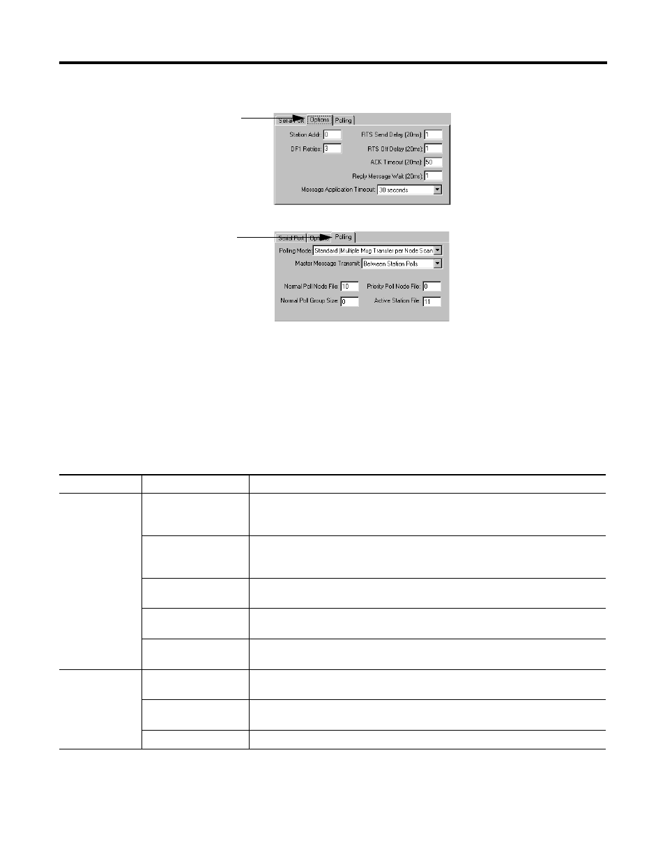
4. Configure Options parameters
5. Configure the Polling
parameters according to
Table 2.3.
6. When all parameters are set,
click OK.
RSLogix 5 Tab
Parameter
Selections
Channel 0
Diagnostic File
Select an unused integer file to store channel status information. You must define a
diagnostic file in order to be able to view channel 0 status. See Table 2.2 on page 2-8 for
description of what’s in this file.
Remote Mode Change
Check enable remote mode change if you want to switch the configuration of the channel
during runtime. Leave the parameter set at the default (unchecked) if you are not using
this feature.
Mode Attention
Character
Select a character that will signal a remote mode change. Leave the parameter set at the
default if you are not using remote mode change.
System Mode Character
Select a character that will signal the channel to switch into system mode. Leave the
parameter set at the default if you are not using remote mode change.
User Mode Character
Select a character that will signal the channel to switch into user mode. Leave the
parameter set at the default if you are not using remote mode change.
Serial Port
Baud Rate
Select a communication rate that all devices in your system support. Configure all
devices in the system for the same communication rate.
Bits Per Character
Match the numbers of bits per character to the devices with which you are
communicating.
Stop Bits
Match the number of stop bits to the devices with which you are communicating.