Rockwell Automation DAG6.5.8 APPLICATION GUIDE SCADA SYSTEM User Manual
Page 283
Publication AG-UM008C-EN-P - February 2005
Configuring Modems 8-17
Cable Pin Assignments
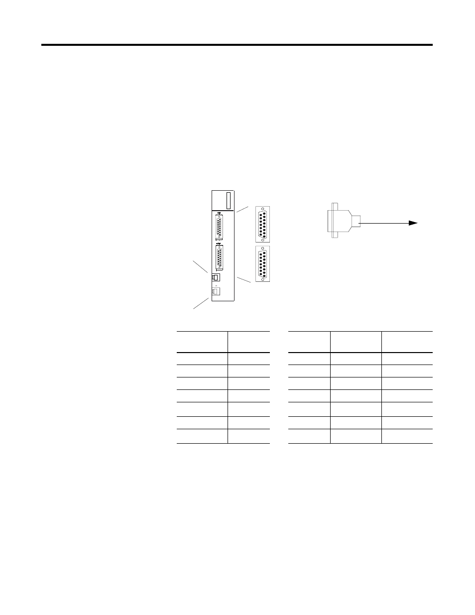
The Model 148-001 requires an RS-232 15-pin male connector with the
pin assignments shown in Figure 8.10 or these MARC cable
assemblies:
•
127-058 (1785-KE to MARC 148-001)
•
127-064 (1785 PLC-5/xx to MARC 148-001)
Figure 8.10 MARC, Inc. Model 148-001
Table 8.15 MARC, Inc. Model 148-001 Pin Assignments
Switch Settings
For Bell 202 full-duplex operating mode, set the switches on
Model 148-001 according to those in Table 8.16. For Bell 202
half-duplex operating mode (point-to-multipoint), set the switches on
Model 148-001 to those in Table 8.17.
MARC
MARC #148-001
Line 2
Line 1
Ports 1 and 2:
15-pin D female
port
2-RJ11 jacks
5 Receive(-)
4 Transmit (-)
3 Transmit (+)
2 Receive (+)
To Allen-Bradley PLC-5/xx
or 1785-KE
Modem
15-pin female
Pin Name
Pin Name
PLC-5
25-pin female
1785-KE
15-pin female
2
TXD.IN
—
TXD.OUT
2
2
3
RXD.OUT
—
RXD.IN
3
3
4
RTS.IN
—
RTS.OUT
4
4
5
CTS.OUT
—
CTS.IN
5
5
7
SIG.GND
—
SIG.GND
7
7
(1)
8
DCD.OUT
—
DCD.IN
8
8
11
DTR.IN
—
DTR.OUT
20
(2)
11
(3)
(1) Pin 7 is jumpered (within the connector) to pin 13.
(2) Pin 20 is jumpered (within the connector) to pin 6.
(3) Pin 11 is jumpered (within the connector) to pin 6.
- 20P PowerFlex DC Drive - Frame D Bimetal Thermostat (10 pages)
- 1336S_F_T_E_R F Frame Snubber Resistor Repl. (6 pages)
- 22-COMM PowerFlex 4-Class DSI (Drive Serial Interface) Network Communication Adapter (4 pages)
- 8-545 Plug In Solid State Relay (2 pages)
- 20-HIM-B1 PowerFlex 7-Class HIM Bezel (DPI) (4 pages)
- 100 Contactors with DC Coil (1 page)
- 100 Contactors with DC Coil (2 pages)
- 20P PowerFlex DC Drive - Frame D Switching Power Supply Circuit Board (6 pages)
- 140G-MTFx_MTHx_MTIx_MTKx Trip Unit Installation-140G-M (6 pages)
- 45BRD Analog Laser Sensor (4 pages)
- 20D Multi-Device Interface Option Board for PowerFlex 700S Drives (20 pages)
- 56RF RFID 18 mm Cylindrical Transceiver (2 pages)
- 42KC Miniature Rectangular: 5V DC Version (2 pages)
- 20P PowerFlex DC Drive - Frame A Switching Power Supply Circuit Board (16 pages)
- 21P-MISC-A-TP-2 Transition Tube Kit #C19-6/7 For PowerFlex 755 w/OEM Liquid Cooling Fr 6/7 Drive (2 pages)
- 42BT Background Suppression Sensor (3 pages)
- 42CB High Speed 18mm Cylindrical (4 pages)
- 140EX-JE2_JE3 Molded Case Circuit Breaker (4 pages)
- 140G-K-EAM1A Early Make Aux Contact for Rotary Handle Oper Mech-140G-K (1 page)
- 140G-K-EAM1A Early Make Aux Contact for Rotary Handle Oper Mech-140G-K (3 pages)
- 20-HIM-A6 PowerFlex (Human Interface Module) (74 pages)
- 42CF General Purpose 12mm Cylindrical (4 pages)
- 20D PowerFlex 700S Phase II Drive Frames 1...6 (80 pages)
- 140EX-HE1_HE2 Molded Case Circuit Breaker (6 pages)
- 140EX-HE1_HE2 Molded Case Circuit Breaker (4 pages)
- 20B PowerFlex 700 Custom Firmware - Pump Off (12 pages)
- 20-WIM-N4S DPI Wireless Interface Module (92 pages)
- 140U H-Frame Circuit Breaker Fixed and Adjustable Thermal Trip (7 pages)
- 140U H-Frame Circuit Breaker Fixed and Adjustable Thermal Trip (2 pages)
- 60-2619, 42JS Swivel/Tilt Mounting Bracket (1 page)
- 22A PowerFlex 4/40/400 Flange Mount (4 pages)
- 45MLA Controller Installation Instructions (16 pages)
- 20P PowerFlex DC Drive - Cooling Fan for Frame A Drives Above 73A at 230V 460V AC (6 pages)
- 42JS Series 7000 to 42JS VisiSight Replacement Kit (2 pages)
- 22A PowerFlex 4-Class HIM Bezel (DSI) (4 pages)
- 42CS Stainless Steel Photoelectric Sensors (4 pages)
- 20L-LL PowerFlex 700L Liquid-to-Liquid Heat Exchanger (40 pages)
- 20P PowerFlex DC Drive - Frame B SCR Modules (20 pages)
- 22B PowerFlex 40 Quick Start FRN 5.xx - 6.xx (161 pages)
- 22B PowerFlex 40 Quick Start FRN 5.xx - 6.xx (22 pages)
- 22F PowerFlex 4M Input RFI Filters (2 pages)
- 45LFM Capacitive Label Sensor (4 pages)
- 140G-Rx Installation Instruction-140G-R (2 pages)
- 140G-Rx Installation Instruction-140G-R (29 pages)
- 22C PowerFlex 400 AC Drive Quick Start - FRN 1-4.xx (28 pages)