Rockwell Automation DAG6.5.8 APPLICATION GUIDE SCADA SYSTEM User Manual
Page 232
Publication AG-UM008C-EN-P - February 2005
7-6 Configuring Logix Controllers
Table 7.1 Serial Port Parameters and Defaults
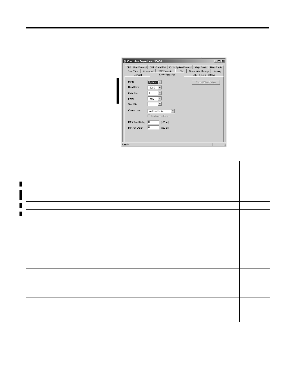
2. Choose the appropriate Serial Port
Channel tab and configure according
to your specification. Serial Port
parameters and defaults can be
found in 7.1.
Parameter
Description
Default
Baud Rate
Specifies the communication rate for the serial port. Select a baud rate that all devices in your system
support.
Select 110, 300, 600, 1200, 2400, 4800, 9600, 19200, or 38400 bits/s.
19200
Parity
Specifies the parity setting for the serial port. Parity provides additional message-packet error
detection. Select Even, Odd, or None.
None
Data Bits
Specifies the number of data bits per message character. Select 7 or 8.
8
Stop Bits
Specifies the number of stop bits per message character. Select 1 or 2.
1
Control Line
Specifies the mode in which the serial driver operates.
Select No Handshake, Full-Duplex, Half-Duplex (with Continuous Carrier unchecked), or Half-Duplex
(with Continuous Carrier checked).
If you are not using a modem, select No Handshake
If both modems in a point-to-point link are full-duplex, select Full-Duplex for both controllers.
If the master modem is full duplex and the slave modem is half-duplex, select Full-Duplex for the
master controller and select Half-Duplex (with Continuous Carrier checked) for the slave controller.
If all the modems in the system are half-duplex, select Half-Duplex (without Continuous Carrier
unchecked) for the controller. See page 7-7 for further details.
No Handshake
RTS Send Delay
Enter a count that represents the number of 20 ms periods of time that elapse between the assertion
of the RTS signal and the beginning of a message transmission. This time delay lets the modem
prepare to transmit a message. The CTS signal must be high for the transmission to occur. See
page 7-7 for further details.
The range is 0 to 32767 periods.
0
RTS Off Delay
Enter a count that represents the number of 20 ms periods of time that elapse between the end of a
message transmission and the de-assertion of the RTS signal. This time delay is a buffer to make sure
the modem successfully transmits the entire message. See page 7-7 for further details.
The range is 0 to 32767 periods. Normally leave at zero.
0