Messaging, Messaging -14 – Rockwell Automation DAG6.5.8 APPLICATION GUIDE SCADA SYSTEM User Manual
Page 218
Publication AG-UM008C-EN-P - February 2005
6-14 Configuring MicroLogix 1000 Controllers
Table 6.2 DF1 Full-Duplex Configuration Parameters MicroLogix 1000
Messaging
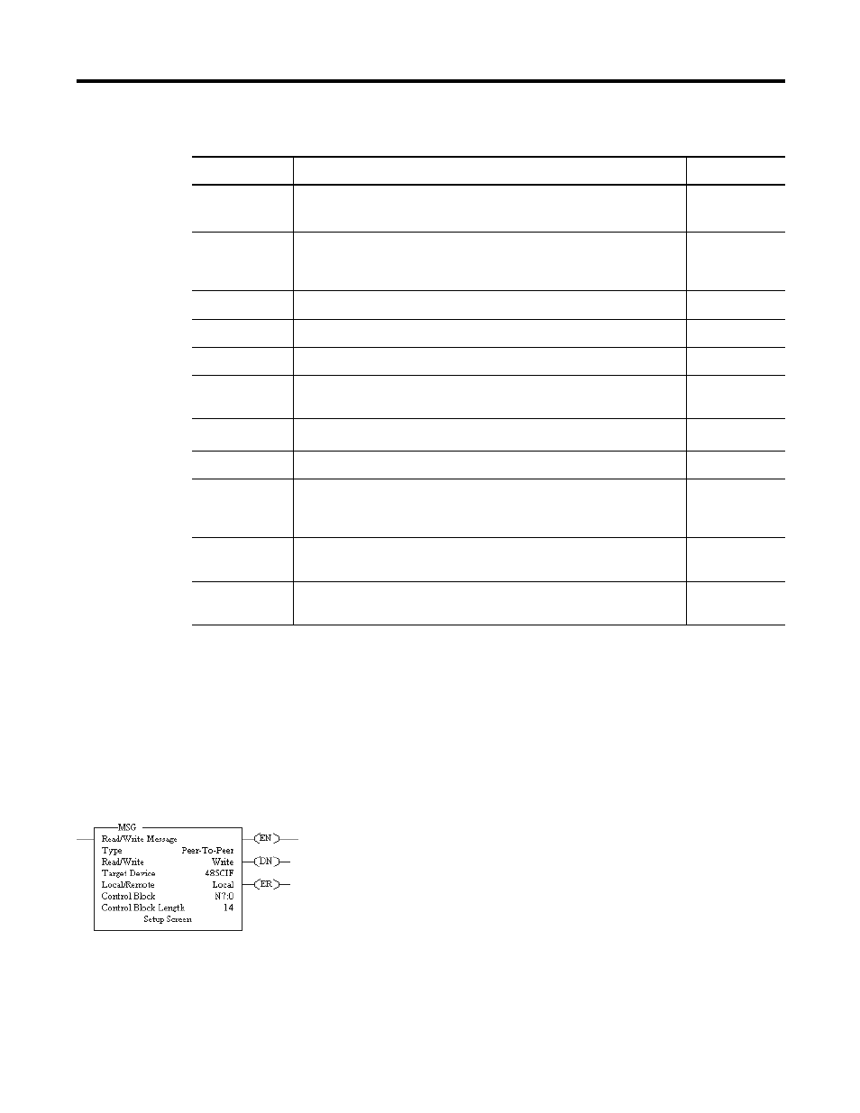
Messaging in a MicroLogix 1000 controller can occur between:
•
a master station and a slave station. For more information see
the chapter pertaining to the master device you are using.
•
a slave station and its master station. See Polled
Report-by-Exception.
•
between two controllers connected via a point-to-point link.
Parameter
Options
Default
Baud Rate
Toggles between the communication rates of 300, 600, 1200, 2400,
4800
(1)
, 9600, 19200, and 38400
9600
(2)
Node Address
Valid range is 0 to 254 decimal for MicroLogix 1000 Series C and later
discrete and all MicroLogix 1000 analog. Not configurable for
MicroLogix 1000 Series A and B discrete.
1
Parity
None
No Parity
Stop Bits
None
1
Error Detection
None
CRC
DLE NAK
Retries
None
N retries
(3)
DLE ENQ Retries
None
N retries
ACK Timeout
None
1 second
Duplicate
Packet
Detection
None
Enabled
Control Line
None
No
Handshaking
Embedded
Responses
None
Enabled
(1) Applicable only to MicroLogix 1000 Series D or later discrete and all MicroLogix 1000 analog controllers.
(2) If retentive communication data is lost, the default is 1200 for MicroLogix 1000 Series A, B, or C discrete only.
For MicroLogix 1000 Series D or later discrete and all MicroLogix 1000 analog, if retentive communication data is lost, baud rate defaults to
9600.
(3) N=255 for MicroLogix 1000 Series A and B discrete.
N=6 for MicroLogix 1000 Series C and later discrete and all MicroLogix 1000 analog.