Configuring channel 0 poll timeout, Configuring channel 0 poll timeout -25, Df1 half-duplex slave channel status -25 – Rockwell Automation DAG6.5.8 APPLICATION GUIDE SCADA SYSTEM User Manual
Page 163: Df1 half-duplex slave channel status
Publication AG-UM008C-EN-P - February 2005
Configuring SLC 5/03, 5/04, and 5/05 Processors 4-25
Configuring Channel 0 Poll
Timeout
The Channel 0 Poll Timeout is only used when the DF1 half-duplex
slave is initiating MSG instructions in ladder logic. This implies that the
master is most likely configured for Standard Polling Mode. The
minimum Poll Timeout value is dependent on the maximum master
poll scan rate. Since the master’s polling and the slave’s triggering of a
MSG instruction are asynchronous events, it is possible that in the
instant just after the slave was polled, the MSG instruction gets
triggered. This means the MSG instruction will remain queued-up for
transmission until the master has polled every other slave first.
Therefore, the minimum slave channel 0 Poll Timeout value is equal
to the maximum master poll scan rate rounded up to the next 20 ms
increment.
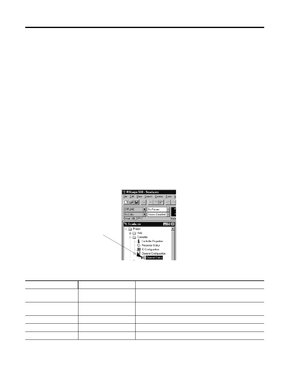
DF1 Half-Duplex Slave Channel Status
Channel Status data is stored in the diagnostic file defined on the
Channel 0 Configuration screen. Table 4.6 on page 4-25 explains
information regarding the diagnostic counter data displayed.
1. Double-click on the Channel
Status icon Located beneath
the Configuration icon to bring
up the Channel Status screen.
Table 4.6 Understanding the DF1 Half-Duplex Slave Status Screen Fields
Status Field
Diagnostic File Location
Definition
DCD Recover
word 11
The number of times the processor detects the DCD handshaking line has
gone low to high
Messages Sent
word 1
The total number of DF1 messages sent by the processor (including
message retries)
Messages Received
word 2
The number of messages received with no errors
Polling Received
word 6
The number of master poll packets received by the processor
Received NAK
word 5
The number of NAKs received by the processor