Lenze ECSCMxxx User Manual
Ä.lkpä
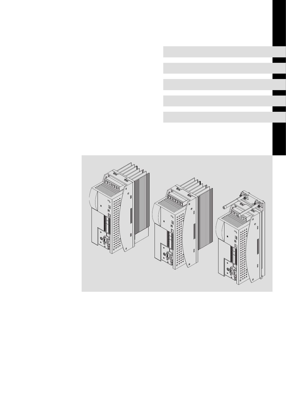
Table of contents
Document Outline
- ECSxM - Axis module "Motion"
- This documentation is valid for ...
- !
- Scope of supply
- Connections and interfaces
- Status displays
- Contents
- 1 Preface and general information
- 2 Safety instructions
- 3 Technical data
- 4 Mechanical installation
- 5 Electrical installation
- 5.1 Installation according to EMC (installation of a CE-typical drive system)
- 5.2 Power terminals
- 5.2.1 Connection to the DC bus (+UG, -UG)
- 5.2.2 Connection plan for mimimum wiring with internal brake resistor
- 5.2.3 Connection plan for mimimum wiring with external brake resistor
- 5.2.4 Motor connection
- 5.2.5 Motor holding brake connection
- 5.2.6 Connection of an ECSxK... capacitor module (optional)
- 5.3 Control terminals
- 5.4 Automation interface (AIF)
- 5.5 Wiring of system bus (CAN)
- 5.6 Wiring of the feedback system
- 6 Commissioning
- 6.1 Before you start
- 6.2 Commissioning steps (overview)
- 6.3 Loading the Lenze setting
- 6.4 Setting of mains data
- 6.5 Entry of motor data for Lenze motors
- 6.6 Holding brake configuration
- 6.7 Setting of the feedback system for position and speed control
- 6.7.1 Resolver as position and speed encoder
- 6.7.2 Resolver as absolute value encoder
- 6.7.3 TTL/SinCos encoder as position and speed encoder
- 6.7.4 TTL/SinCos encoder as position encoder and resolver as speed encoder
- 6.7.5 Absolute value encoder as position and speed encoder
- 6.7.6 Absolute value encoder as position encoder and resolver as speed encoder
- 6.8 Selecting the control interface (C4010)
- 6.9 Process data to the axis module (control word Ctrl1 and setpoints)
- 6.10 Process data from the axis module (status words and actual values)
- 6.11 Entry of machine parameters
- 6.12 Configuring the digital inputs and outputs
- 6.13 Setting of homing parameters
- 6.14 Selection of the operating mode
- 6.15 Controller enable (CINH = 0)
- 6.16 Following error monitoring (C3030, C3031)
- 6.17 Evaluating and retracting from hardware limit switch
- 6.18 Quick stop (QSP)
- 6.19 Operation with motors from other manufacturers
- 6.20 Optimising the drive behaviour after start
- 7 Parameter setting
- 8 Configuration
- 8.1 Configuring MotionBus/system bus (CAN)
- 8.1.1 Setting CAN node address and baud rate
- 8.1.2 Individual addressing
- 8.1.3 Defining boot-up master in the drive system
- 8.1.4 Setting of boot-up time/cycle time
- 8.1.5 Executing a reset node
- 8.1.6 Axis synchronisation (CAN synchronisation)
- 8.1.7 Monitoring of the synchronisation (sync time slot)
- 8.1.8 Axis synchronisation via CAN
- 8.1.9 Axis synchronisation via terminal X6/DI1
- 8.2 Node guarding
- 8.3 Diagnostics codes
- 8.4 Remote parameterisation (gateway function)
- 8.1 Configuring MotionBus/system bus (CAN)
- 9 Monitoring functions
- 9.1 Fault responses
- 9.2 Overview of monitoring functions
- 9.3 Configuring monitoring functions
- 9.3.1 Monitoring times for process data input objects
- 9.3.2 Time-out monitoring for activated remote parameterisation
- 9.3.3 Short circuit monitoring (OC1)
- 9.3.4 Earth fault monitoring (OC2)
- 9.3.5 Motor temperature monitoring (OH3, OH7)
- 9.3.6 Heatsink temperature monitoring (OH, OH4)
- 9.3.7 Monitoring of internal device temperature (OH1, OH5)
- 9.3.8 Function monitoring of thermal sensors (H10, H11)
- 9.3.9 Current load of controller (I x t monitoring: OC5, OC7)
- 9.3.10 Current load of motor (I2 x t monitoring: OC6, OC8)
- 9.3.11 DC-bus voltage monitoring (OU, LU)
- 9.3.12 Voltage supply monitoring - control electronics (U15)
- 9.3.13 Motor phase failure monitoring (LP1)
- 9.3.14 Monitoring of the resolver cable (Sd2)
- 9.3.15 Motor temperature sensor monitoring (Sd6)
- 9.3.16 Monitoring of the absolute value encoder initialisation (Sd7)
- 9.3.17 Sin/cos signal monitoring (Sd8)
- 9.3.18 Monitoring of the speed system deviation (nErr)
- 9.3.19 Monitoring of max. system speed (NMAX)
- 9.3.20 Monitoring of the rotor position adjustment (PL)
- 10 Diagnostics
- 11 Troubleshooting and fault elimination
- 12 Appendix
- 13 Index