Commissioning – Lenze ECSCMxxx User Manual
Page 150
Commissioning
Setting of homing parameters
Homing modes
l
150
EDBCSXM064 EN 11.0
Modes 10 and 11
Approaching the hardware limit switch, reversing and travelling towards touch probe
signal.
)
Note!
ƒ
While reversing, the hardware limit switch approached must be assigned
(mechanics must be designed accordingly).
ƒ
In a 6 ms cycle, the negative/positive hardware limit switches are queried.
TP
1
5
3
R
2
4
0
ECSXA515
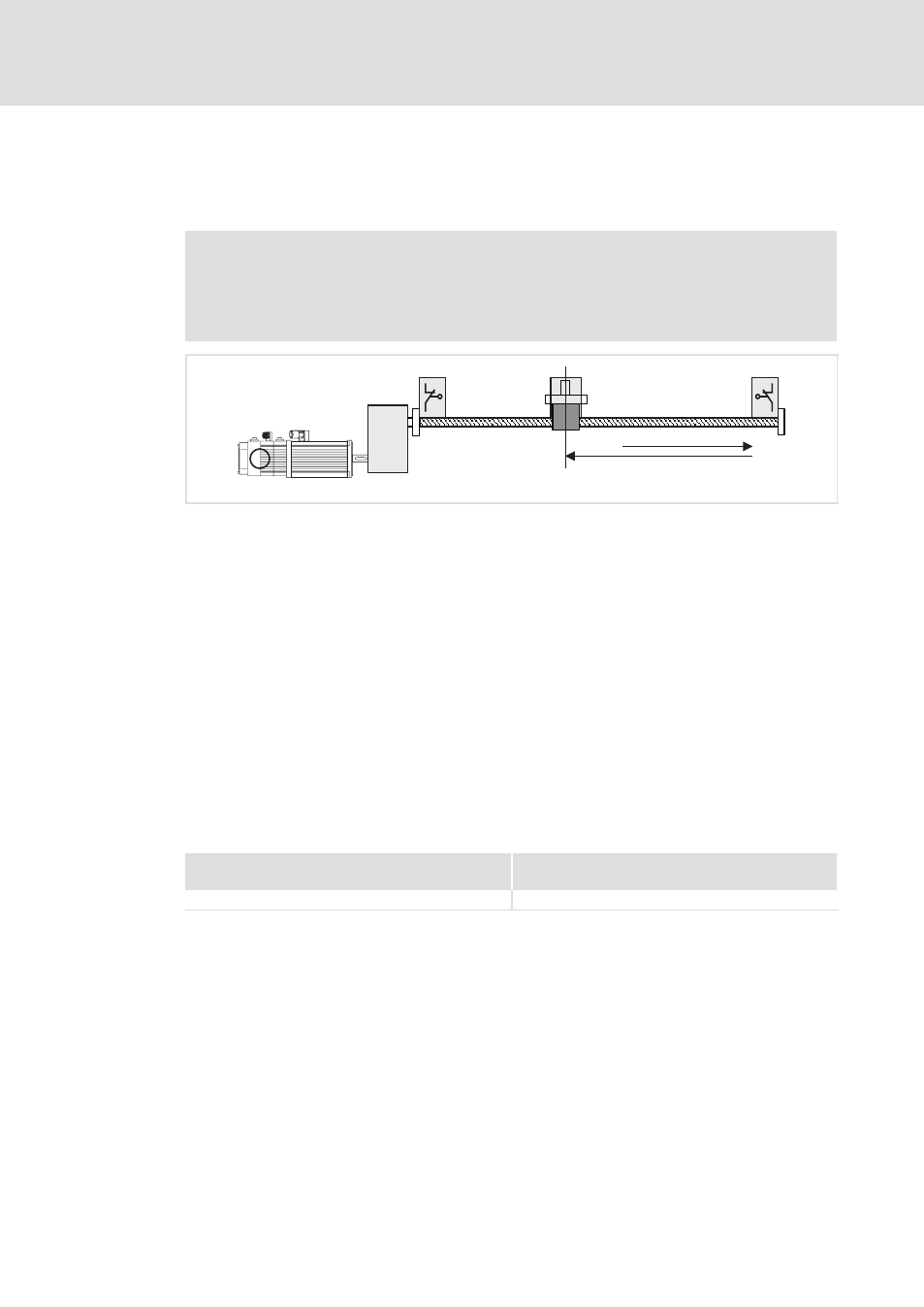
Fig. 6−21
Homing in mode 10
0 Negative hardware limit switch
1 Touch probe signal (touch probe sensor)
2 Positive hardware limit switch
3 Load (e.g. slide)
4 Home position
5 Direction of travel
The touch probe is used if the zero pulse (zero position) of the position encoder occurs
non−reproducibly at the same position due to the mechanical structure. It is also possible
that the zero pulse is mechanically shifted after a motor exchange.
The load (e. g. slide) from its initial position is traversed to a hardware limit switch. During
this process, no fault message is actuated. According to the direction of travel, a reversal
takes place at the hardware limit switch approached, and the load is traversed to the touch
probe signal. This touch probe signal bears the home position. If the drive already is at the
hardware limit switch before homing, the direction of travel is reversed immediately.
Settings
Mode 10
(Homing towards the positive hardware limit switch)
Mode 11
(Homing towards the negative hardware limit switch)
l
Set C3010 = 10.
l
Set C3010 = 11.