2 homing modes, Homing modes, Commissioning – Lenze ECSCMxxx User Manual
Page 145
Commissioning
Setting of homing parameters
Homing modes
l
145
EDBCSXM064 EN 11.0
6.13.2
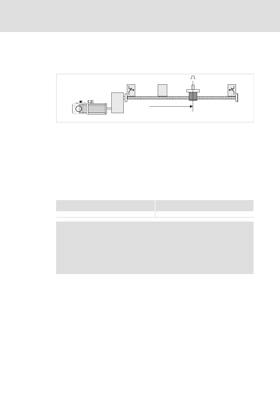
Homing modes
Modes 0 and 1
Travelling to zero pulse (zero position of the position encoder) via the reference switch.
Ref
1
2
4
5
6
3
R
0
ECSXA510
Fig. 6−16
Homing in mode 0
0 Negative hardware limit switch
1 Reference switch
2 Zero pulse (zero position of the position encoder)
3 Positive hardware limit switch
4 Load (e. g. slide)
5 Direction of travel
6 Home position
The load (e. g. slide) travels from its starting position beyond the reference switch to the
first zero pulse after leaving the reference switch. This zero pulse bears the home position.
Before homing, the load may be positioned on the reference switch.
Settings
Mode 0
(Homing towards the positive hardware limit switch)
Mode 1
(Homing towards the negative hardware limit switch)
l
Set C3010 = 0.
l
Set C3010 = 1.
)
Note!
ƒ
Single−turn absolute value encoder (SinCos encoder) and resolver do not
have a zero pulse. Here the zero position corresponds to the zero pulse
.
ƒ
In case of multi−turn absolute value encoders, only the homing modes
6 ... 11 and 99 can be used (C3010 = 6 ... 11 or 99).
ƒ
If the digital frequency output (X8) is to be used as encoder simulation with
zero pulse, set C0540=2.