Commissioning – Lenze ECSCMxxx User Manual
Page 149
Commissioning
Setting of homing parameters
Homing modes
l
149
EDBCSXM064 EN 11.0
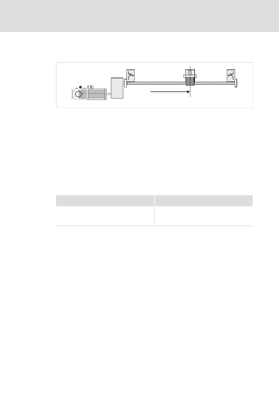
Modes 8 and 9
Travelling to touch probe signal.
TP
1
5
3
R
2
4
0
ECSXA514
Fig. 6−20
Homing in mode 8
0 Negative hardware limit switch
1 Touch probe signal (touch probe sensor)
2 Positive hardware limit switch
3 Load (e.g. slide)
4 Direction of travel
5 Home position
The touch probe is used if the zero pulse (zero position of the position encoder) does not
occur reproducibly at the same position due to the mechanical structure. It is also possible
that the zero pulse is mechanically shifted after a motor replacement.
The load (e.g. slide) travels from its original position to the first touch probe signal which
lies in the direction of travel. This touch probe signal bears the home position.
Settings
Mode 8
(Homing towards the positive hardware limit switch)
Mode 9
(Homing towards the negative hardware limit switch)
l
Set C3010 = 2.
l
If the touch probe signal is already applied to
X6/DI2, first of all retracting towards the positive
hardware limit switch is performed.
l
Set C3010 = 3.
l
If the touch probe signal is already applied to
X6/DI2, first of all retracting towards the negative
hardware limit switch is performed.