Commissioning – Lenze ECSCMxxx User Manual
Page 148
Commissioning
Setting of homing parameters
Homing modes
l
148
EDBCSXM064 EN 11.0
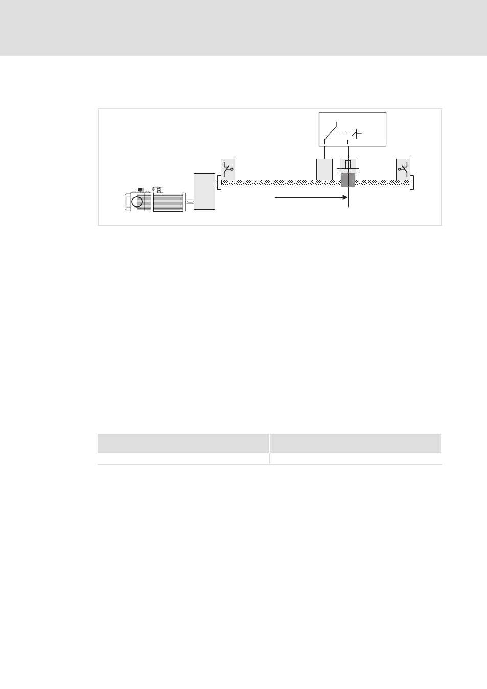
Mode 6 and 7
Travelling to touch probe signal via reference switch.
TP
1
5
3
R
4
6
0
0
1
Ref
2
X6/DI2
X6/DO1
ECSXA513
Fig. 6−19
Homing in mode 6
0 Negative hardware limit switch
1 Reference switch
2 Touch probe signal (touch probe sensor)
3 Positive hardware limit switch
4 Load (e.g. slide)
5 Direction of travel
6 Home position
The touch probe is used if the zero pulse (zero position of the position encoder) does not
occur reproducibly at the same position due to the mechanical structure. It is also possible
that the zero pulse is mechanically shifted after a motor replacement.
The load (e.g. slide) travels from its original position beyond the reference switch to the
first touch probe signal after leaving the reference switch. This touch probe signal bears
the home position. A HIGH level is pending at the digital input X6/DI2. Before homing, the
load may already be situated on the reference switch.
Use X6/DO1 to switch a relay which changes over between reference switch and touch
probe sensor at X6/DI2. (
^ 68)
Settings
Mode 6
(Homing towards the positive hardware limit switch)
Mode 7
(Homing towards the negative hardware limit switch)
l
Set C3010 = 6.
l
Set C3010 = 7.