2 diagnostics with gdo, Diagnostics with gdo, Diagnostics – Lenze ECSCMxxx User Manual
Page 255
Diagnostics
Diagnostics with Global Drive Oscilloscope (GDO)
Diagnostics with GDO
l
255
EDBCSXM064 EN 11.0
10.2.2
Diagnostics with GDO
1. Connect axis module to the PC/laptop.
– Connection to terminal X14 (system bus (CAN)) with a PC system bus adapter.
2. Supply the axis module with a control voltage of 24 V (
^ 64).
3. Start the GDO on the PC/Laptop.
4. Click on the [ Connect device ] button.
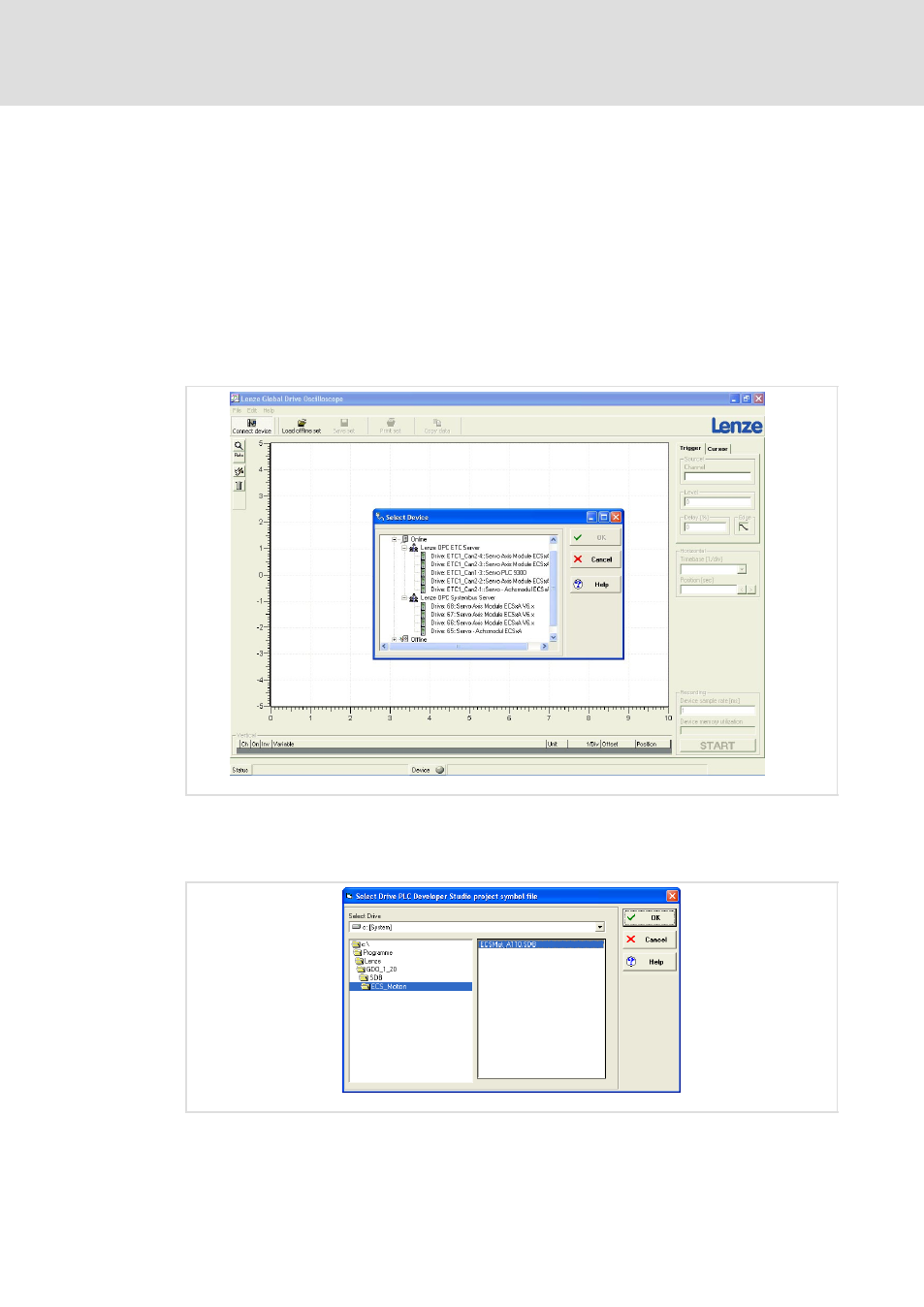
– The dialog "Select Device" opens (Fig. 10−5).
– The devices connected to the bus are listed under "Online".
ECSXA561
Fig. 10−5
GDO view: Dialog "Select Device"
5. Select the corresponding device under "Online" and click on the [ OK ] button.
– The dialog "Select Drive PLC Developer Studio project symbol file" opens:
ECSXA562
Fig. 10−6
GDO view: Dialog "Select Drive PLC Developer Studio project symbol file"
6. Select symbol file ECSMot_Axxx.SDB (xxx = version number) and click on the [ OK ]
button.