1 toggle-bit monitoring, Toggle−bit monitoring, Commissioning – Lenze ECSCMxxx User Manual
Page 136: 1 toggle−bit monitoring
Commissioning
Process data from the axis module (status words and actual values)
Toggle−bit monitoring
l
136
EDBCSXM064 EN 11.0
6.10.1
Toggle−bit monitoring
Drive
IN
OUT
Higher-level motion control
PDO
IN
OUT
Error
handling
PDO
IN
OUT
Error
handling
PDO
IN
OUT
Error
handling
Toggle-Bit
Interrupted if
controller is
not enabled
Interrupted if
controller is
not enabled
Interrupted if
controller is
not enabled
Toggle bit
monitoring
Toggle bit
monitoring
Toggle bit
monitoring
Controller 1
Controller 2
Controller n
Controller
enable
Toggle bit
generator
ECSXA501
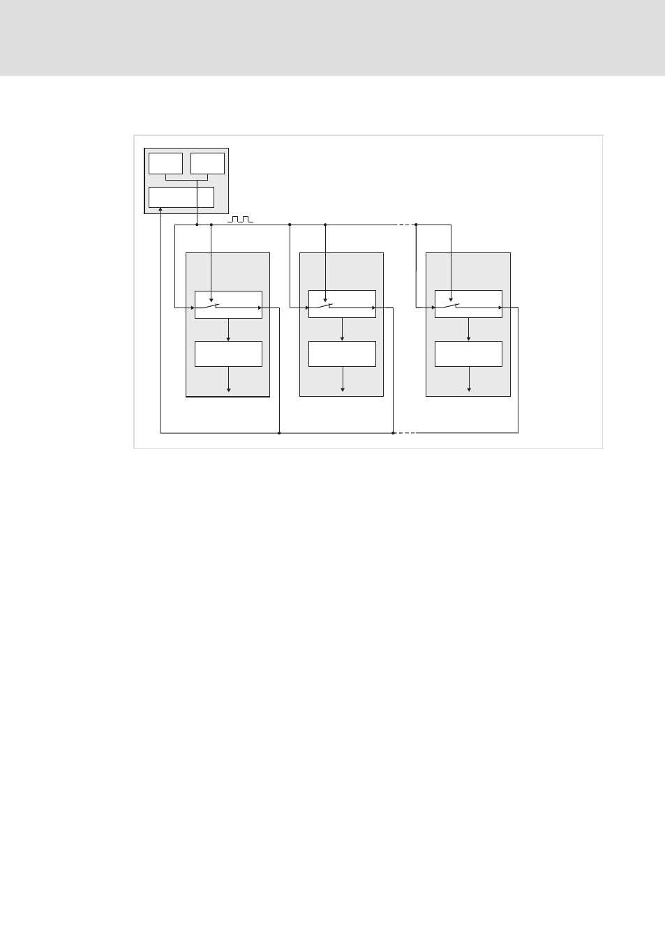
Fig. 6−12
Basic principle of toggle bit monitoring
Toggle bit monitoring serves to monitor the sync−controlled transfer of telegrams on the
fieldbus.
The higher−level motion control generates a signal which alternates between low and high
(toggle bit). This bit pattern is transmitted cyclically to all controllers of the drive system via
a process data channel of the MotionBus (CAN, EtherCAT).
Each controller monitors the state change of the toggle bit and simultaneously returns the
bit pattern 1 : 1 to the control. If errors occur in the drive system, every controller involved
carries out an independent error evaluation.
In the event of an error (e.g. if a telegram is not transmitted) the toggle bit error counter
is increased by 1. Depending on the error counter limit (C3161) and the fault response
(C3160) all controllers involved can react irrespective of the communication (error
handling).
The toggle bit monitoring function is only active if enabled via the control bit Ctrl1.Bit07
by the higher−level motion control. Furthermore, the toggle bit signal is only returned to
the control system if this mode is selected.