Commissioning – Lenze ECSCMxxx User Manual
Page 146
Commissioning
Setting of homing parameters
Homing modes
l
146
EDBCSXM064 EN 11.0
Modes 2 and 3
Approaching the hardware limit switch, reversing the direction of travel and travelling to
the zero position (zero position of the position encoder) via the reference switch.
)
Note!
ƒ
While reversing, the approached hardware limit switch must be assigned
(mechanics must be designed accordingly).
ƒ
In a 6 ms cycle, the negative/positive hardware limit switches are queried.
Ref
1
5
3
R
2
4
6
0
ECSXA511
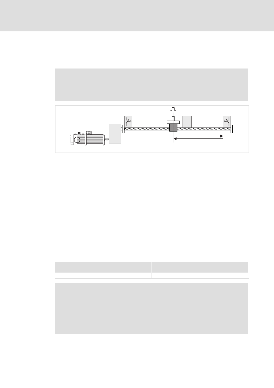
Fig. 6−17
Homing in mode 2
0 Negative hardware limit switch
1 Zero pulse (zero position of the position encoder)
2 Reference switch
3 Positive hardware limit switch
4 Load (e. g. slide)
5 Direction of travel
6 Home position
The load (e.g. slide) from its initial position is traversed to a hardware limit switch. During
this process, no fault message is actuated. According to the direction of travel, a reversal
takes place at the hardware limit switch approached, and the load, after leaving the
reference switch, is traversed to the first zero pulse beyond the reference switch. This zero
pulse bears the home position. If the drive has already approached a hardware limit switch
before homing, the direction of travel is reversed immediately.
In the homing modes 2 and 3, the reference switch is safely found since if the worst comes
to the worst, the entire travel range will be executed.
Settings
Mode 2
(Homing towards the positive hardware limit switch)
Mode 3
(Homing towards the negative hardware limit switch)
l
Set C3010 = 2.
l
Set C3010 = 3.
)
Note!
ƒ
Single−turn absolute value encoder (SinCos encoder) and resolver do not
have a zero pulse. Here the zero position corresponds to the zero pulse
.
ƒ
In case of multi−turn absolute value encoders, only the homing modes
6 ... 11 and 99 can be used (C3010 = 6 ... 11 or 99).
ƒ
If the digital frequency output (X8) is to be used as encoder simulation with
zero pulse, set C0540=2.