Setting the digital input, 2 digital output, Setting the digital output – Kramer Electronics WP-501 User Manual
Page 73: Figure 113: gpi/o threshold window
68
K-Config - Assigning the Peripheral Devices to Master and Auxiliary Device Ports
Setting the Digital Input
In this example, an alarm setting causes a short circuit, thus activating a trigger.
To set the trigger:
1.
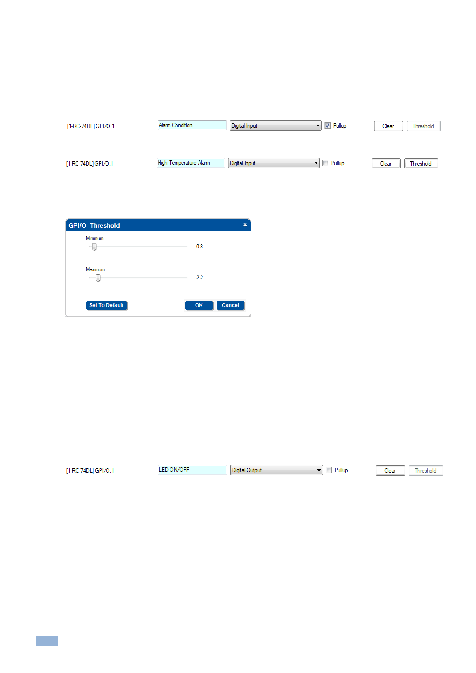
Define the GPI/O in the Port Manager.
Check Pullup for short circuit detection; the threshold is set automatically (skip step 2):
Do not check Pullup for voltage level detection; the threshold to be set by the user (proceed to step 2):
2.
Click the Threshold button to define the GPI/O Threshold (minimum from 0 and maximum up to 30V)
according to the indication set by the device (other voltages will not activate the trigger).
Figure 113: GPI/O Threshold Window
To learn more about GPI/O Events, go to
Section
7.2.2
Digital Output
The digital output function is defined by the pull-up setup:
Without Pullup: The port will act as a solid state relay (open/close functions)
The GPI/O maximum voltage is 30V DC and the maximum current is 50mA
With Pullup: the port can be used as a TTL positive logic output (open: ~2.4V; closed:~0.2V)
Setting the Digital Output
Define the GPI/O in the Port Manager:
Once defined as Digital Output, the GPI/O port will appear in the Action Editor > Port Switch, and can be used like any
other relay: