Figure 66: testing serial commands, Connecting the pc to the room controller, Figure 67: testing serial commands – Kramer Electronics WP-501 User Manual
Page 44: Selecting a device port, Figure 68: testing serial commands, Ethernet settings for auxiliary device, Figure 66, Figure 67
K-Config
–
The Driver Manager
– Getting Started
39
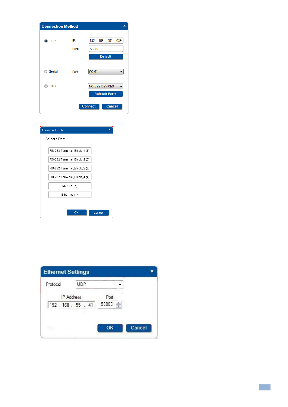
Figure 66: Testing Serial Commands
–Connecting the PC to the Room Controller
Figure 67: Testing Serial Commands
–Selecting a Device Port
4.
Select the port to which the device is connected to the room controller (for example, the projector is connected
via RS-232 Terminal Block 1 to the RC-74DL room controller) and click OK.
Note that if the auxiliary device is connected to the Ethernet, the following window appears. Verify the details
and then click OK
Figure 68: Testing Serial Commands
–Ethernet Settings for Auxiliary Device
The command tested is sent to the Auxiliary device. The request text box shows the sent command and the Response
text box shows the response: