Figure 89: the port manager window for rc-74dl, Figure 90: the auxiliary device window – Kramer Electronics WP-501 User Manual
Page 59
54
K-Config - Defining the Control Room via the Project Navigator
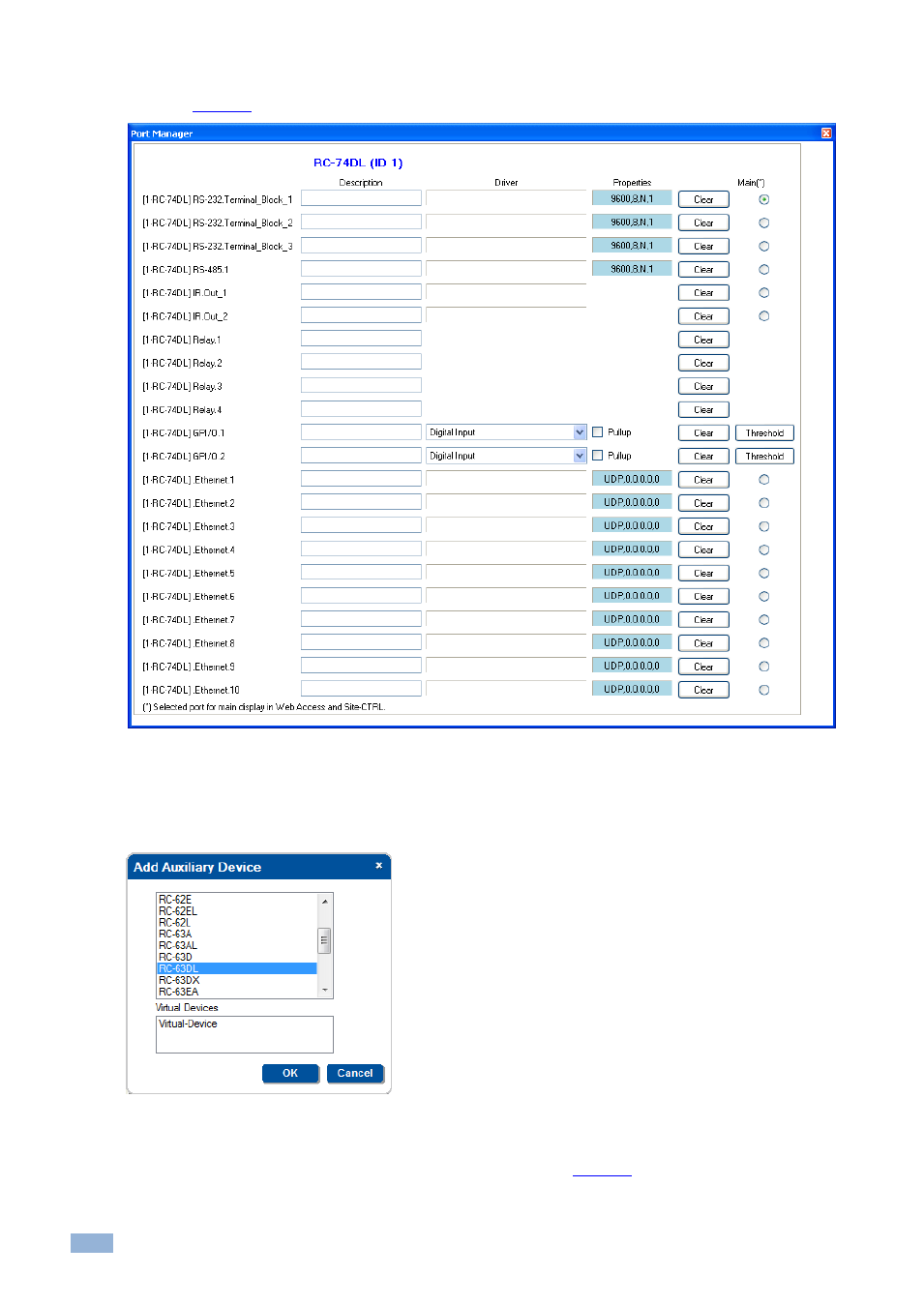
In the same way, the Port Manager window (which does not appear in the default layout) lists the RC-74DL relevant
Figure 89: The Port Manager Window for RC-74DL
3.
Select the Master device (1
– RC-74DL) and Click + again. Select an auxiliary device (for example, RC-63DL)
from the Add Auxiliary Device list and click OK.
You can also add the auxiliary device by right clicking the Master Room Controller label, RC-74DL in this example. Right
clicking also lets you delete the master device and auxiliary devices, add a description and set the K-
NET™ ID.
Figure 90: The Auxiliary Device Window
The RC-63DL front panel appears in the Device View area and the Action Editor shows the ports and
commands relevant to both the RC-74DL and the RC-63DL (see
). The Port Manager presents the
ports relevant to the RC-63DL.