Figure 86: the project navigator window – Kramer Electronics WP-501 User Manual
Page 57
52
K-Config - Defining the Control Room via the Project Navigator
6
Defining the Control Room via the Project Navigator
You are here:
Configuration Steps
Description
Section
Introduction
General information and system requirements
Planning
Carefully plan your controlled room
Installation
Install the Software
Introduction to K-Config
Get to know the K-Config main window, menus and quick access icons
Driver Manager
Define the Peripheral Device Drivers
Project Navigator
Define the Controlled Room
Port Manager
Assign the peripheral devices to the Master and Auxiliary device ports
Triggers
Activate the Triggers
Adding Actions
Describes how to add the various actions to a trigger
Connecting to a Device
Describes how to connect to a device, upgrade the firmware, read/write to the device
and so on
Once you have arranged and defined the driver commands of the peripheral devices, you can set the control room via
the project navigator.
The project navigator lets you set the controlled room.
Depending on the Master RC, up to four Aux K-NET devices and two Virtual Devices can be used in the same control
setup. At any point you can right click a control device to perform further functions.
We recommend that you open a new project before defining the control room. At any point, you can save (or
save as) the project, see
In the following example the RC-74DL is selected as the Master room controller and the RC-63DL is the connected
auxiliary panel (some of the devices in the Add Device list (for example, the WP-500) do not accept auxiliary devices).
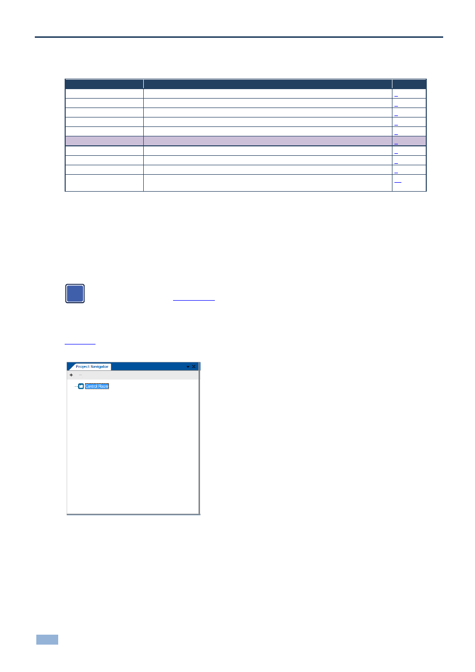
shows the Project Navigator window. You can right-click the Control Room label to rename it or add a
Master Device
Figure 86: The Project Navigator Window
i