Rainbow Electronics W90P710CDG User Manual
Page 49
W90P710CD/W90P710CDG
Publication Release Date: September 19, 2006
- 49 -
Revision B2
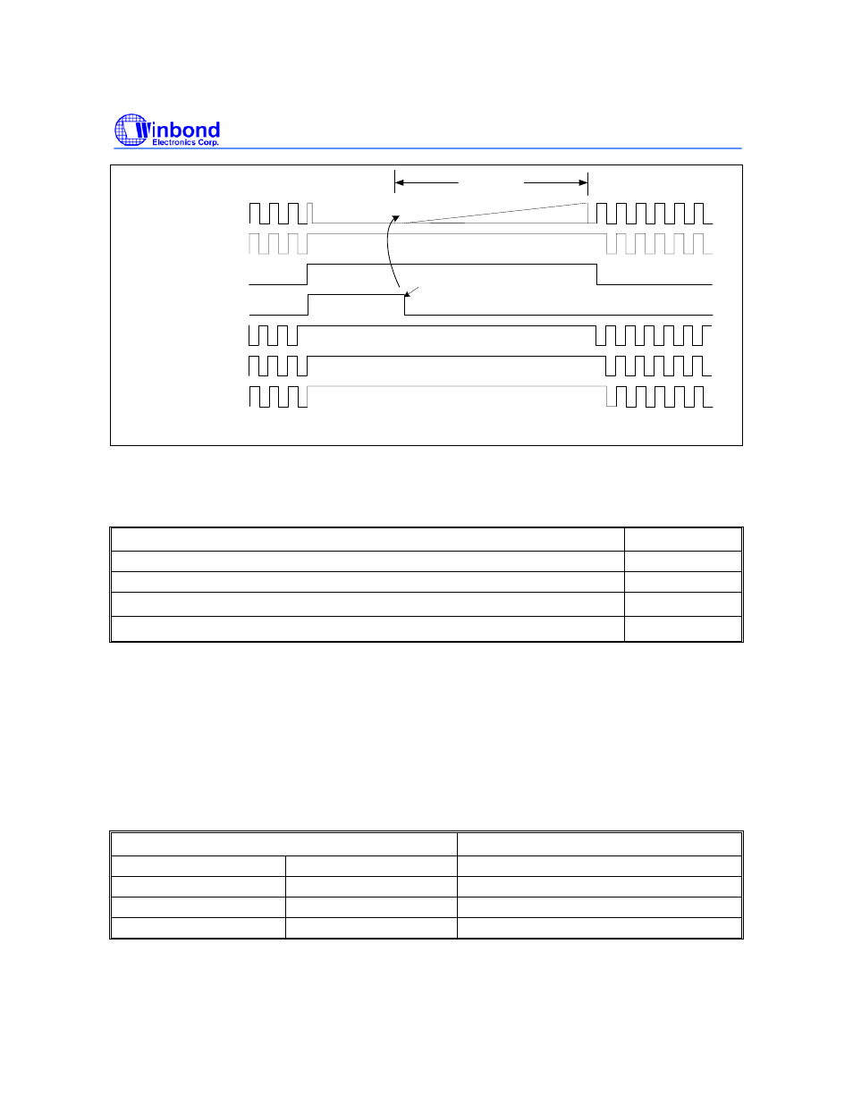
HCLK
(cache)
Case3. IDLE=0, PD=1, MIDLE=0
EXTAL
idle _state
pd_state
65536 clocks
HCLK
wake up by pheripheral's
interrupts
Fig 6.2.9 Clock management for system power down mode and wake up
6.2.7 Power-On
Setting
After power on reset, there are eight Power-On setting pins to configure W90P710 system configuration.
POWER-ON SETTING
PIN
Internal System Clock Select
D15
Little/Big Endian Mode Select
D14
Boot ROM/FLASH Data Bus Width
D [13:12]
Default (Always pull-up in normal operation)
D [11:8]
D15 pin:Internal System Clock Select
If pin D15 is pull-down, the external clock from EXTAL pin is served as internal system clock.
If pin D15 is pull-up, the PLL output clock is used as internal system clock.
D14 pin:Little/Big Endian Mode Select
If pin D14 is pull-down, the external memory format is Big Endian mode.
If pin D14 is pull-up, the external memory format is Little Endian mode.
D [13:12] : Boot ROM/FLASH Data Bus Width
D [13:12]
BUS WIDTH
Pull-down Pull-down
8-bit
Pull-down Pull-up
16-bit
Pull-up Pull-down
32-bit
Pull-up Pull-up
RESERVED