Rainbow Electronics W90P710CDG User Manual
Page 313
W90P710CD/W90P710CDG
Publication Release Date: September 19, 2006
- 313 -
Revision B2
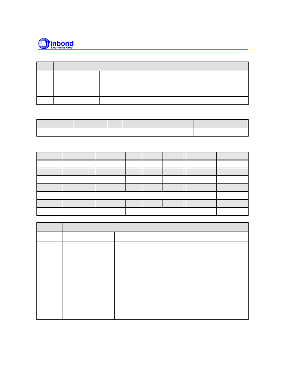
Continued.
BITS
DESCRIPTIONS
[2:1] BLOCK_EN[1:0]
Audio interface type selection
• If BLOCK_EN[0]=0/1, IIS interface is disable/enable
• If BLOCK_EN[1]=0/1, AC-link interface is disable/enable
The BLOCK_EN[1:0] bits are read/write
[0]
Reserved
Sub-block reset control register (ACTL_RESET)
REGISTER
ADDRESS
R/W
DESCRIPTION
RESET VALUE
ACTL_RESET
0xFFF0_9004 R/W
Sub block reset control
0x0000_0000
The value in ACTL_RESET register control the reset operation in each sub block.
BITS
DESCRIPTIONS
[31:17]
Reserved -
[16]
ACTL_RESET
Audio controller reset control bit
1 = the whole audio controller is reset
0 = the audio controller is normal operation
The ACTL_RESET bit is read/write
[15:14]
RECORD_SINGLE
[1:0]
record single/dual channel select bits
2’b11= the record is dual channel
2’b01= the record only select left channel
2’b10= the record only select right channel
2’b00 is reserved
Note that, when ADC is selected as record path, it only
support left channel record.
The PLAY_SINGLE[1:0] bits are read/write
31
30
29
28
27
26
25
24
23
22
21
20
19
18
17
16
ACTL_RESET
15
14
13
12
11
10
9
8
RECORD_SINGLE[1:0] PLAY_SINGLE[1:0]
Reserved
AC_RECORD
7
6
5
4
3
2
1
0
AC_PLAY IIS_RECORD IIS_PLAY
Reserved
AC_RESET IIS_RESET