Rainbow Electronics W90P710CDG User Manual
Page 249
W90P710CD/W90P710CDG
Publication Release Date: September 19, 2006
- 249 -
Revision B2
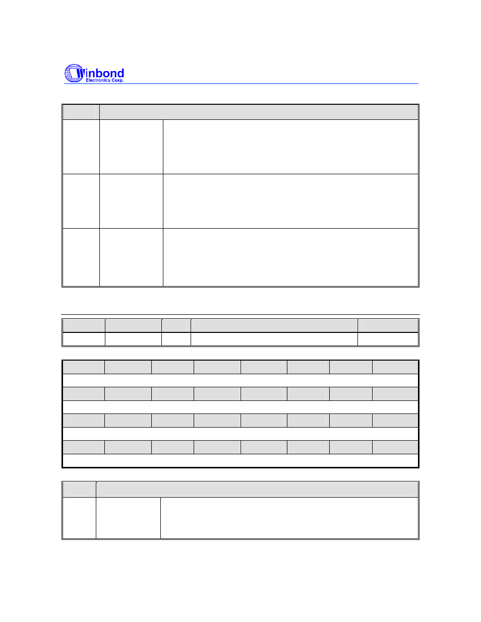
Continued.
BITS
DESCRIPTIONS
[2]
CD_IS
CD# Interrupt Status
0=No Interrupt Generated
1=Interrupt Generated
Note: Write “1” into this bit will clear the interrupt status.
[1]
DO_IS
Data Output Interrupt Status
0=No Interrupt Generated
1=Interrupt Generated
Note: Write “1” into this bit will clear the interrupt status.
[0]
DI_IS
Data Input Interrupt Status
0=No Interrupt Generated
1=Interrupt Generated
Note: Write “1” into this bit will clear the interrupt status.
SD Command Argument Register (SDAUG)
REGISTER
ADDRESS
R/W
DESCRIPTION
RESET VALUE
SDARG
0xFFF0_7310
R/W
SD Command Argument Register
0x0000_0000
31
30
29
28
27
26
25
24
SD_CMD_ARG
23
22
21
20
19
18
17
16
SD_CMD_ARG
15
14
13
12
11
10
9
8
SD_CMD_ARG
7
6
5
4
3
2
1
0
SD_CMD_ARG
BITS
DESCRIPTIONS
[31:0]
SD_CMD_ARG
SD Command Argument
This register contains a 32-bit value specifies the argument of SD
command from host controller to card.