FUJITSU MB91F109 FR30 User Manual
Page 389
365
16.7 Execution Status of the Automatic Algorithm
Table 16.7-1 lists the possible statuses of the hardware sequence flag.
[bit 7] DPOLL (Data polling)
❍
Automatic write operation status
When a read operation is performed during execution of the automatic write algorithm, flash
memory outputs the inversion of the last written data. When read access is performed at the
end of the automatic write algorithm, flash memory outputs the data of bit 7 of the read data in
the address indicated by the address signal.
❍
Automatic erase operation status
When a read operation is performed during execution of the automatic erase algorithm, flash
memory outputs "0" irrespective of the address indicated by the address signal. Similarly, flash
memory outputs "1" at the end of the algorithm.
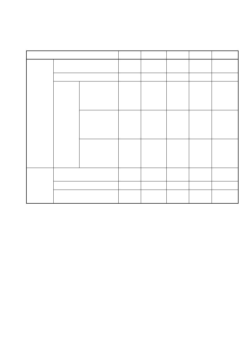
Table 16.7-1 Statuses of the Hardware Sequence Flag
Status
DPOLL
TOGGLE
TLOVER
SETIMR
TOGGL2
Executing
Automatic read operation
Reverse
data
Toggle
0
0
1
Automatic erase operation
0
Toggle
0
1
Toggle
Temporary
erase stop
mode
Temporary erase
stop and read
(from sectors in
temporary erase
stop)
1
1
0
0
Toggle*
1
Temporary erase
stop and read
(from sectors not
in temporary
erase stop)
Data
Data
Data
Data
Data
Temporary erase
stop and write (to
sectors not in
temporary erase
stop)
Reverse
data
Toggle*
2
0
0
1*
3
Time limit
exceeded
Automatic write operation
Reverse
data
Toggle
1
0
1
Automatic erase operation
0
Toggle
1
1
Undefined
Write operation during
temporary erase stop
0
Toggle
1
1
Undefined
*1:
Bit 2 toggles for consecutive read operations from sectors in temporary erase stop.
*2:
Bit 6 toggles for consecutive read operations from any address.
*3:
During temporary erase stop and write operations, bit 2 indicates "1" while reading the address for
the write operation. However, bit 2 toggles for consecutive read operations from sectors in temporary
erase stop.