FUJITSU MB91F109 FR30 User Manual
Page 381
357
16.4 Sector Configuration of Flash Memory
16.4 Sector Configuration of Flash Memory
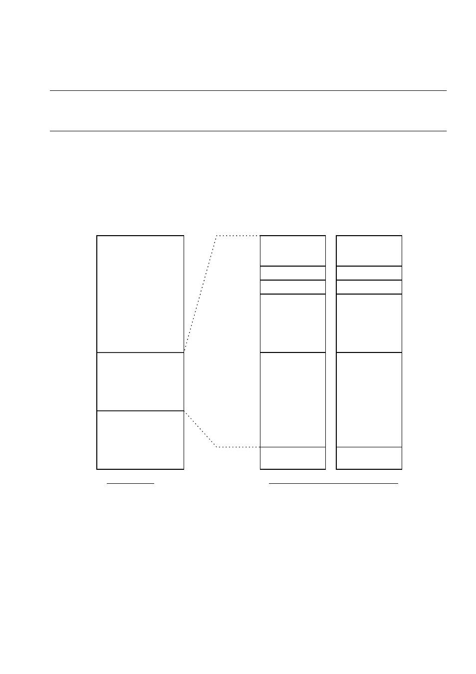
Figure 16.4-1 shows the sector configuration of the flash memory. Table 16.4.1 lists
the respective sector addresses.
■
Sector Configuration of the Flash Memory
Flash memory address mapping for access from the FR-CPU is different from the mapping for
access from the ROM writer. This section shows the mapping for access from the CPU.
Figure 16.4-1 Memory Map and Sector Configuration
SA4(16Kbyte)
SA3(8Kbyte)
SA2(8Kbyte)
SA1(32Kbyte)
SA0(63Kbyte)
SA5(63Kbyte)
SA6(32Kbyte)
SA7(8Kbyte)
SA8(8Kbyte)
SA9(16Kbyte)
31
16
15
0
FFFFFFFFh
RAM(1Kbyte)
RAM(1Kbyte)
10000h
0C0800h
0FFFFC-Dh
0F8000-1h
0F7FFC-Dh
0F4000-1h
0F3FFF-Dh
0F0000-1h
0EFFFC-Dh
0E0000-1h
0DFFFC-Dh
0C0800-1h
0C07FC-Dh
0C0000-1h
0FFFFE-Fh
0F8002-3h
0F7FFE-Fh
0F4002-3h
0F3FFE-Fh
0F0002-3h
0EFFFE-Fh
0E0002-3h
0DFFFE-Fh
0C0802-3h
0C07FE-Fh
0C0002-3h
Flash memory area
MSB side 16 bits
LSB side 16 bits
Memory map
Sector configuration (SA = sector address)
- XG Series P3NK-4452-01ENZD (614 pages)
- FPCAC14C (1 page)
- MCJ3230SS (161 pages)
- MBA3073NC (138 pages)
- T5140 (102 pages)
- T5140 (76 pages)
- MAM3367MC/MP (152 pages)
- MPC3045AH (185 pages)
- MB2142-02 (23 pages)
- MB15F86UL (6 pages)
- MHS2030AT (40 pages)
- MHW2100BS (296 pages)
- MHK2060AT (227 pages)
- Disk Drives MHK2060AT (227 pages)
- MCM3064SS (170 pages)
- Mainboard D1561 (45 pages)
- MHC2040AT (219 pages)
- D1961 (45 pages)
- DISK DRIVES MHM2100AT (231 pages)
- MHR2010AT (250 pages)
- MHZ2120BJ (320 pages)
- MCE3064AP (175 pages)
- LQFP-64P (16 pages)
- Solaris PCI GigabitEthernet 3.0 (115 pages)
- MAY2036RC (94 pages)
- MAB3091 (142 pages)
- MPE3XXXAT (191 pages)
- MHV2040AH (40 pages)
- MHW2040AC (278 pages)
- ETERNUSmgr P2X0-0202-01EN (64 pages)
- VSS Hardware Provider 2.1 (134 pages)
- MAG3182FC (61 pages)
- MAU3147NC/NP (130 pages)
- MAX3147RC (94 pages)
- MHV2160BT (296 pages)
- MHV2040AT (280 pages)
- MAW3300NC/NP (130 pages)
- DeskPower E623 (50 pages)
- MAG3182LC (133 pages)
- OPTICAL DISK DRIVES MDG3064UB (42 pages)
- MHF2021AT (225 pages)
- MHR2040AT (40 pages)
- Single Drive FTM7926FB (1 page)
- PG-FCS103 (98 pages)
- MAS3735FC (114 pages)