5 external interrupt operation – FUJITSU MB91F109 FR30 User Manual
Page 240
216
CHAPTER 6 EXTERNAL INTERRUPT/NMI CONTROLLER
6.5
External Interrupt Operation
After the external level register and enable interrupt request register are set, the
request set in the ELVR register is input to the corresponding pin. This module then
issues an interrupt request signal to the interrupt controller.
■
External Interrupt Operation
If multiple interrupt requests are issued to the interrupt controller, their priorities are checked. If
the priority of the interrupt request issued by this resource is the highest, an interrupt occurs.
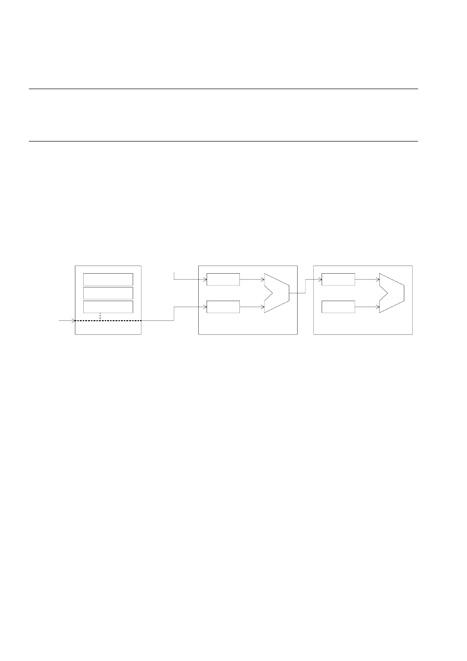
Figure 6.5-1 shows external interrupt operation.
Figure 6.5-1 External Interrupt Operation
■
Returning from Stop State
When an external interrupt is used to return from the stop state in clock stop mode, select the H
level for the input request. Selecting the L level may result in a malfunction.
The edge request cannot be used to return from the stop state in clock stop mode.
■
External Interrupt Operation Procedure
To set the registers used for external interrupts, proceed as follows:
1. Disable the applicable bit of the interrupt enable register.
2. Set the applicable bit of the interrupt level register.
3. Clear the applicable bit of the interrupt request register.
4. Enable the applicable bit of the interrupt enable register.
The settings in 3) and 4) can be performed simultaneously using 16-bit data.
When setting the registers in this module, disable the interrupt enable register in advance. Also,
clear the interrupt request register before enabling the interrupt enable register to prevent an
interrupt from occurring inadvertently when registers are set or when interrupts are enabled.
CPU
ELVR
ICR
yy
IL
EIRR
CMP
CMP
ENIR
ICR
xx
ILM
External interrupt
Resource
request
Interrupt controller
Cause