FUJITSU MB91F109 FR30 User Manual
Page 163
139
4.16 Relationship between Data Bus Widths and Control Signals
4.16 Relationship between Data Bus Widths and Control Signals
Data bus control signals (WR0X-WR1X, CS0H, CS0L, CS1L, CS1H, DW0X, and DW1X)
always correspond to data bus byte locations on a one-to-one basis, regardless of big
and little endians and data bus widths.
■
Relationship between Data Bus Widths and Control Signals
The following outlines the byte locations of the data buses of this part number used in the
specified data bus width and the control signals corresponding to those locations for each bus
mode.
❍
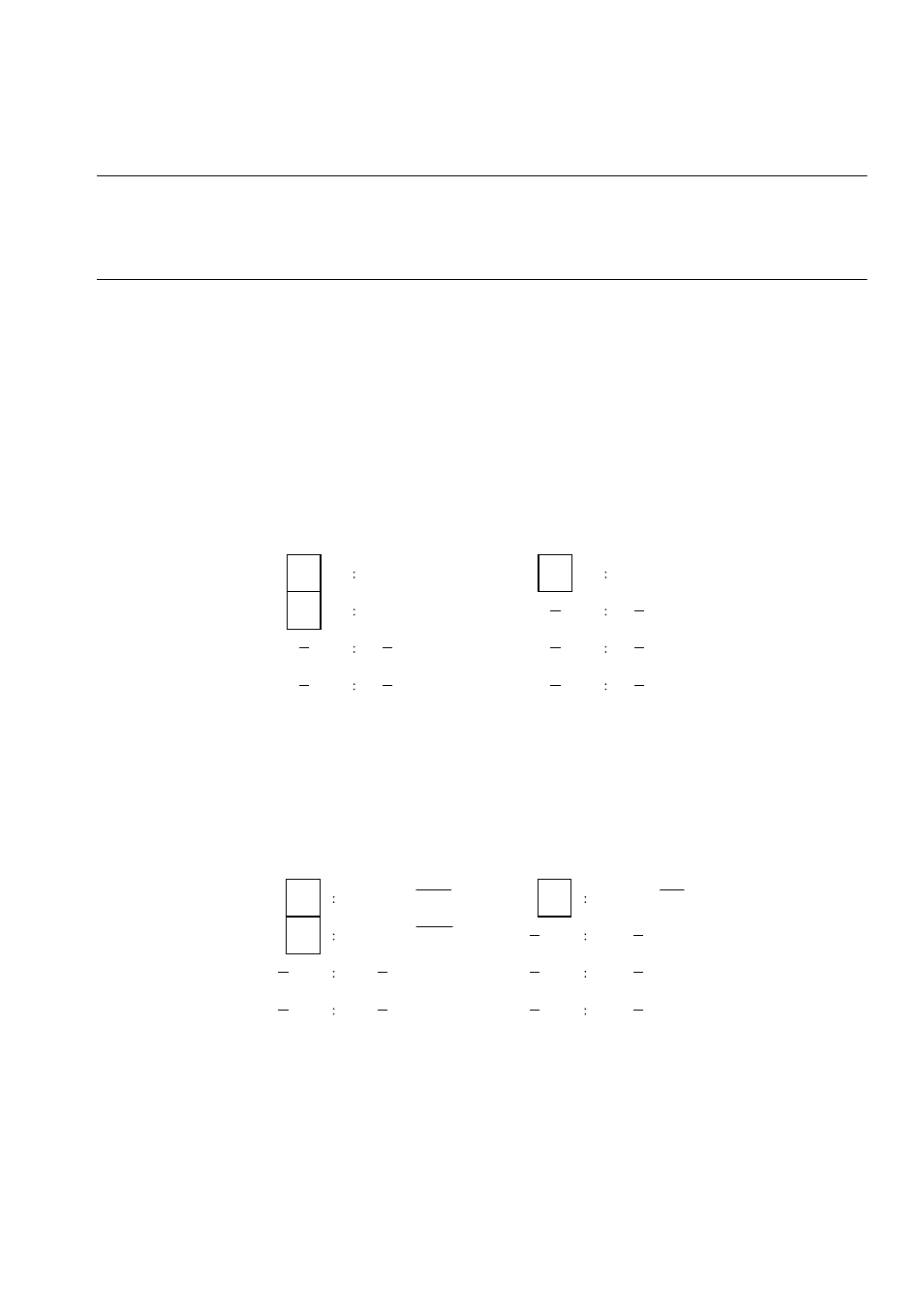
Data bus widths and control signals for usual bus interface
Figure 4.16-1 Data bus Widths and Control Signals in Usual Bus Interface
❍
Data bus widths and control signals in DRAM interface
Figure 4.16-2 Data Bus Widths and Control Signals in DRAM Interface
Table 4.16-1 outlines the bus widths and control signals.
Data bus
Control signal
Control signal
D31
D31
WR0X
WR0X
D24
WR1X
D16
Data bus
16-bit bus width
(D23 to D16 are unused.)
8-bit bus width
D31
D31
CASL WEL
CAS WE
D24
CASH WEH
D16
Data bus
Control signal
Control signal
Data bus
16-bit bus width
8-bit bus width
(D23 to D16 are unused.)