4 operation of 16-bit reload timer – FUJITSU MB91F109 FR30 User Manual
Page 311
287
12.4 Operation of 16-Bit Reload Timer
12.4 Operation of 16-Bit Reload Timer
The 16-bit reload timer performs the following two types of operation:
• Internal clock operation
• Underflow operation
■
Internal Clock Operation
When a frequency division clock of the internal clock is used to run the timer, a machine clock
frequency divided by 2, 8, or 32 can be selected as the clock source.
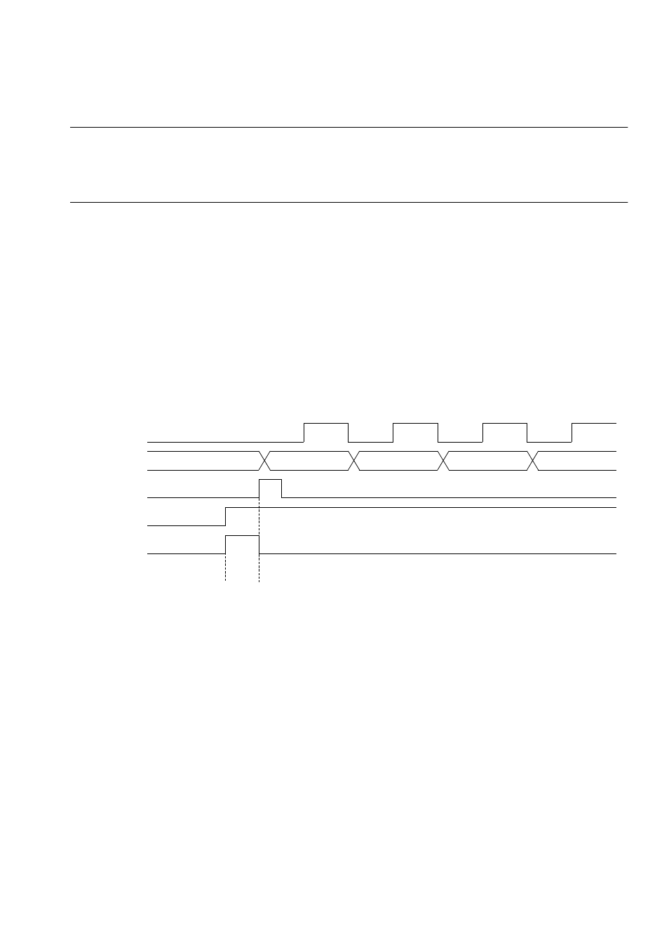
To make the counter start counting immediately when counting is enabled, set both the CNTE
and TRG bits of the control status register to "1". The trigger input by the TRG bit is always
effective, regardless of the operation mode, when the timer is active (CNTE = "1").
Figure 12.4-1 is a counter start and operation timing chart.
Time T (peripheral clock machine cycle) is required from when a counter start trigger is input to
when the reload register data is loaded to the counter.
Figure 12.4-1 Counter Start and Operation Timing
■
Underflow Operation
An underflow occurs when the counter value changes from 0000
H
to FFFF
H
. That is, an
underflow occurs at a count of "reload register value + 1."
If the RELD bit of the control register is "1" when an underflow occurs, the value in the reload
register is loaded to the counter and the counter continues counting. When the RELD bit is "0",
the counter stops at FFFF
H
.
When an underflow occurs, the UF bit of the control register is set, and an interrupt request is
issued when the INTE bit is "1".
Figure 12.4-2 is a timing chart for underflow operation timing.
T
- 1
- 1
- 1
Count clock
Counter
Data loading
CNTE (register)
TRG (register)
Reload data