FUJITSU MB91F109 FR30 User Manual
Page 286
262
CHAPTER 10 UART
■
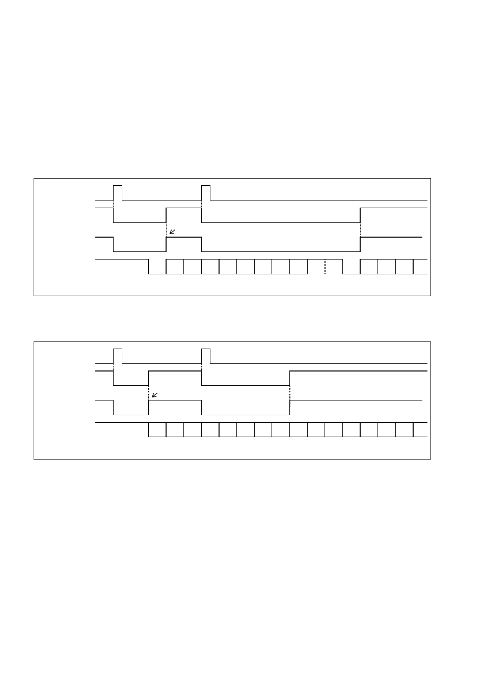
Interrupt Flag Set Timing for Data Transmission in Mode 0, 1, or 2
TDRE is cleared when data is written to the SODR register. After the written data is transferred
to the internal shift register and the SODR register is ready to accept the next item of write data,
TDRE is set again to issue an interrupt request to the CPU.
When "0" is written to TXE (or RXE in mode 2) of the SCR register during transmission, TDRE
of the SSR register is set to "1", thereby stopping the transmission shifter and inhibiting UART
transmit operation. When a "0" is written to TXE (or RXE in mode 2) of the SCR register during
transmission, data written to the SODR register before transmission is stopped is transmitted.
Figure 10.9-4 TDRE Set Timing (Mode 0 or 1)
Figure 10.9-5 TDRE Set Timing (Mode 2)
TDRE
ST D0 D1 D2 D3 D4 D5 D6 D7 SP SP ST D0 D1 D2 D3
A/D
SO interrupt
SO output
ST: Starter bit
D0 to D7: Data bit
SP: Stop bit
A/D: Address/data multiplexer
Writing to SODR
An interrupt request is issued to the CPU.
TDRE
D0 D1 D2 D3 D4 D5 D6 D7 D0 D1 D2 D3 D4 D5 D6 D7
SO interrupt
SO output
D0 to D7: Data bit
Writing to SODR
An interrupt request is issued to the CPU.