2 u-timer registers – FUJITSU MB91F109 FR30 User Manual
Page 265
241
9.2 U-TIMER Registers
9.2
U-TIMER Registers
The following three U-TIMER registers are used:
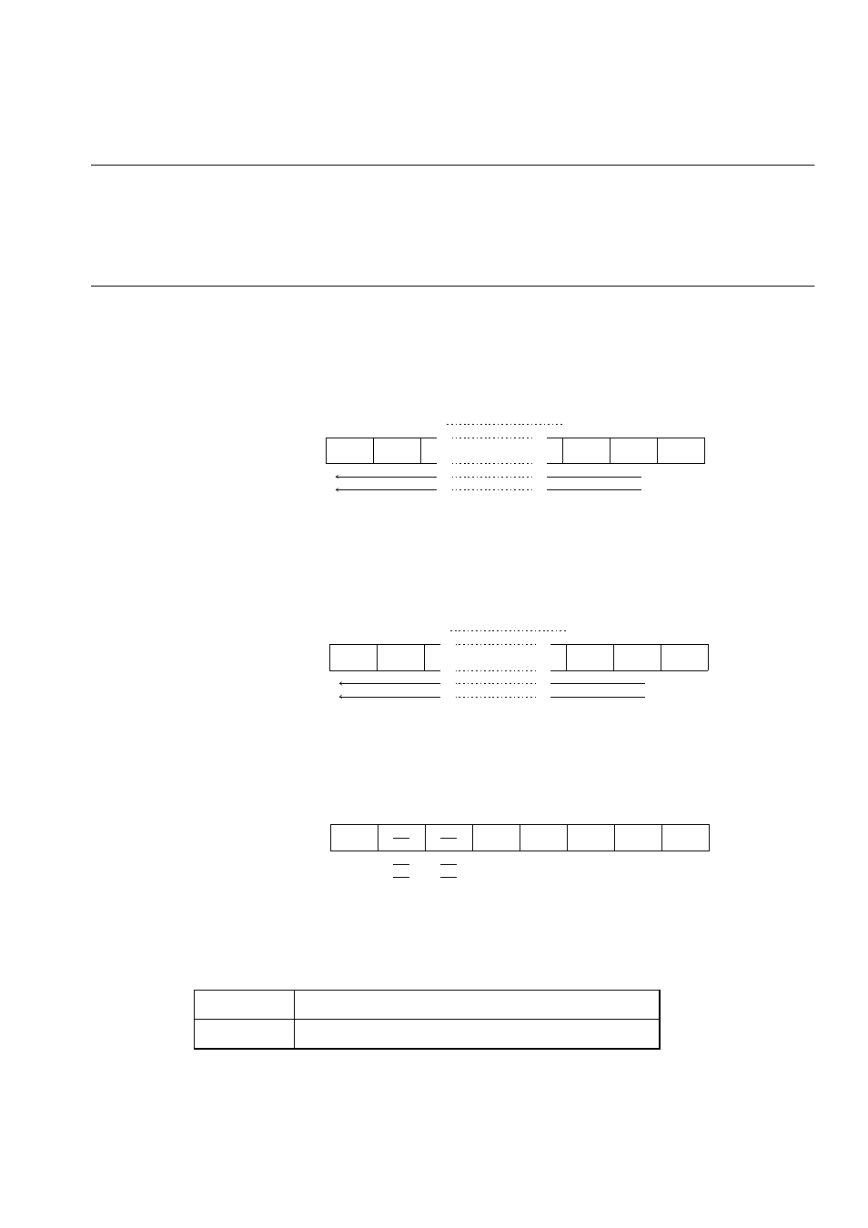
• U-TIMER (UTIM)
• Reload register (UTIMR)
• U-TIMER control register (UTIMC)
■
U-TIMER (UTIM)
The UTIM indicates the timer value. Access it using a 16-bit transfer instruction.
■
Reload register (UTIMR)
The UTIMR stores the value to be reloaded to the UTIM when the UTIM underflows.
Access it using a 16-bit transfer instruction.
■
U-TIMER Control Register (UTIMC)
The UTIMC controls the U-TIMER operation.
[bit 7] UCC1 (U-timer Count Control 1)
The UCC1 bit controls the U-TIMER counting method.
n: Value set in UTIMR
α
: Cycle of clock output to UART
15
14
2
1
0
UTIM
ch0 Address:0000
0078
H
b15
b14
b2
b1
b0
ch1 Address:0000
007C
H
ch2 Address:0000
0080
H
R
0
Access
initial value
15
14
2
1
0
UTIMR
ch0
Address:0000
0078
H
b15
b14
b2
b1
b0
ch1
Address:0000
007C
H
ch2
Address:0000
0080
H
W
0
initial value
Access
7
6
5
4
3
2
1
0
U T I M C
c h 0
A d d r e s s : 0 0 0 0 0 0 7 B
H
U C C 1
U T I E U N D R C L K S U T S T U T C R
c h 1
A d d r e s s : 0 0 0 0 0 0 7 F
H
c h 2
A d d r e s s : 0 0 0 0 0 0 8 3
H
R / W
R / W
R / W
R / W
R / W
R / W
0
0
0
0
0
1
Access
Initial value
0
Normal operation.
α
= 2n+2 [initial value]
1
+1 mode
α
= 2n+3