12 reset source hold circuit – FUJITSU MB91F109 FR30 User Manual
Page 125
101
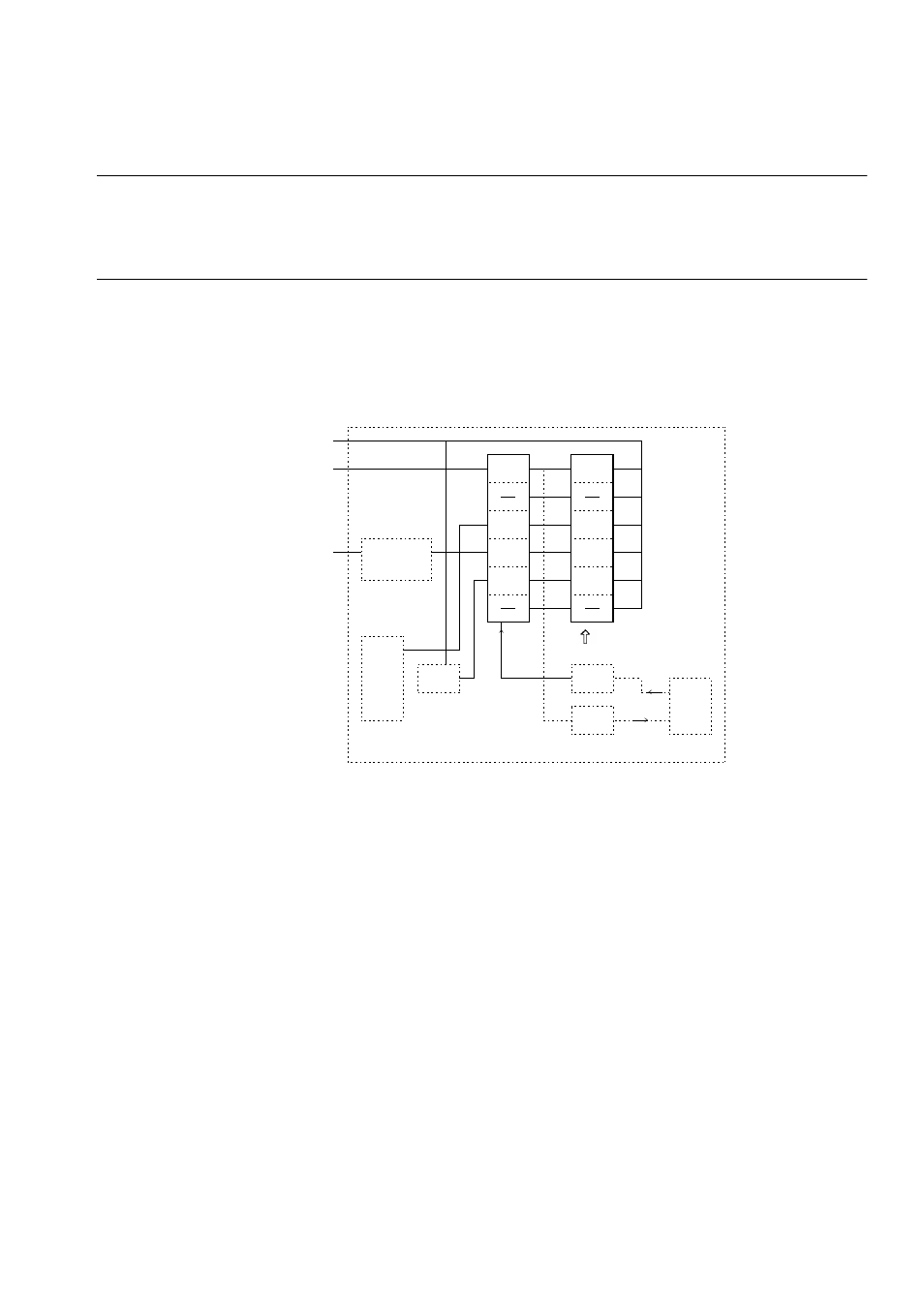
3.12 Reset Source Hold Circuit
3.12 Reset Source Hold Circuit
The reset source hold circuit holds the source of previous resetting. Reading the
circuit clears all flags to 0. Once a source flag is set, it is not cleared unless the circuit
is read.
■
Block Diagram of Reset Source Hold Circuit
Figure 3.12.1 is a block diagram of the reset source hold circuit.
Figure 3.12-1 Block Diagram of Reset Source Hold Circuit
■
Setting for Reset Source Holding
No special settings are required to use the reset source hold function. Provide an instruction to
read the reset source register and an instruction to branch to the appropriate program, at the
beginning of the program to be placed at the reset entry address.
PONR
PONR
WDOG
WDOG
ERST
ERST
SRST
SRST
clr
SRST
STCR
.or.
Internal bus
From power-on cell
RSTX pin
RSTX
input circuit
W
atchdog reset
detection circuit
State = RST
Initialized
by reading
Decoder
State
transi-
tion
circuit
- XG Series P3NK-4452-01ENZD (614 pages)
- FPCAC14C (1 page)
- MCJ3230SS (161 pages)
- MBA3073NC (138 pages)
- T5140 (102 pages)
- T5140 (76 pages)
- MAM3367MC/MP (152 pages)
- MPC3045AH (185 pages)
- MB2142-02 (23 pages)
- MB15F86UL (6 pages)
- MHS2030AT (40 pages)
- MHW2100BS (296 pages)
- MHK2060AT (227 pages)
- Disk Drives MHK2060AT (227 pages)
- MCM3064SS (170 pages)
- Mainboard D1561 (45 pages)
- MHC2040AT (219 pages)
- D1961 (45 pages)
- DISK DRIVES MHM2100AT (231 pages)
- MHR2010AT (250 pages)
- MHZ2120BJ (320 pages)
- MCE3064AP (175 pages)
- LQFP-64P (16 pages)
- Solaris PCI GigabitEthernet 3.0 (115 pages)
- MAY2036RC (94 pages)
- MAB3091 (142 pages)
- MPE3XXXAT (191 pages)
- MHV2040AH (40 pages)
- MHW2040AC (278 pages)
- ETERNUSmgr P2X0-0202-01EN (64 pages)
- VSS Hardware Provider 2.1 (134 pages)
- MAG3182FC (61 pages)
- MAU3147NC/NP (130 pages)
- MAX3147RC (94 pages)
- MHV2160BT (296 pages)
- MHV2040AT (280 pages)
- MAW3300NC/NP (130 pages)
- DeskPower E623 (50 pages)
- MAG3182LC (133 pages)
- OPTICAL DISK DRIVES MDG3064UB (42 pages)
- MHF2021AT (225 pages)
- MHR2040AT (40 pages)
- Single Drive FTM7926FB (1 page)
- PG-FCS103 (98 pages)
- MAS3735FC (114 pages)