3 bus interface – FUJITSU MB91F109 FR30 User Manual
Page 140
116
CHAPTER 4 BUS INTERFACE
4.3
Bus Interface
The bus interface include the following:
• Usual bus interface
• DRAM interface
These interfaces can only be used in the predetermined area.
■
Chip Select Areas and Bus Interfaces
Table 4.3.1 shows the correspondence between each chip select area and available interface
functions.
The area mode register (AMD) specifies which interface to use. When not specified, the usual
bus interface is selected.
❍
DRAM interface
Two channels of DRAM interface are prepared and use areas 4 and 5.
•
3 types of DRAM interface
•
Double CAS DRAM (usual DRAM interface)
•
Single CAS DRAM
•
Hyper DRAM
•
High-speed page mode
•
Selection of 2CAS/1WE and 1CAS/2WE
•
CBR refresh system
•
Selfrefresh mode
•
Output of RAS and CAS programmable waveforms
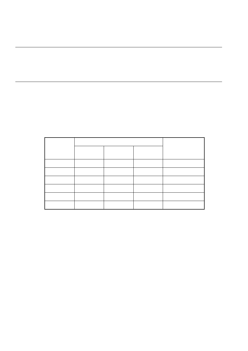
Table 4.3-1 Correspondence between Chip Select Areas and Selectable Bus Interfaces
Area
Selectable bus interface
Remarks
Usual bus
Time
sharing
DRAM
0
O
-
-
Reset time
1
O
-
-
2
O
-
-
3
O
-
-
4
O
-
O
5
O
-
O
- XG Series P3NK-4452-01ENZD (614 pages)
- FPCAC14C (1 page)
- MCJ3230SS (161 pages)
- MBA3073NC (138 pages)
- T5140 (102 pages)
- T5140 (76 pages)
- MAM3367MC/MP (152 pages)
- MPC3045AH (185 pages)
- MB2142-02 (23 pages)
- MB15F86UL (6 pages)
- MHS2030AT (40 pages)
- MHW2100BS (296 pages)
- MHK2060AT (227 pages)
- Disk Drives MHK2060AT (227 pages)
- MCM3064SS (170 pages)
- Mainboard D1561 (45 pages)
- MHC2040AT (219 pages)
- D1961 (45 pages)
- DISK DRIVES MHM2100AT (231 pages)
- MHR2010AT (250 pages)
- MHZ2120BJ (320 pages)
- MCE3064AP (175 pages)
- LQFP-64P (16 pages)
- Solaris PCI GigabitEthernet 3.0 (115 pages)
- MAY2036RC (94 pages)
- MAB3091 (142 pages)
- MPE3XXXAT (191 pages)
- MHV2040AH (40 pages)
- MHW2040AC (278 pages)
- ETERNUSmgr P2X0-0202-01EN (64 pages)
- VSS Hardware Provider 2.1 (134 pages)
- MAG3182FC (61 pages)
- MAU3147NC/NP (130 pages)
- MAX3147RC (94 pages)
- MHV2160BT (296 pages)
- MHV2040AT (280 pages)
- MAW3300NC/NP (130 pages)
- DeskPower E623 (50 pages)
- MAG3182LC (133 pages)
- OPTICAL DISK DRIVES MDG3064UB (42 pages)
- MHF2021AT (225 pages)
- MHR2040AT (40 pages)
- Single Drive FTM7926FB (1 page)
- PG-FCS103 (98 pages)
- MAS3735FC (114 pages)