5 counter states – FUJITSU MB91F109 FR30 User Manual
Page 313
289
12.5 Counter States
12.5 Counter States
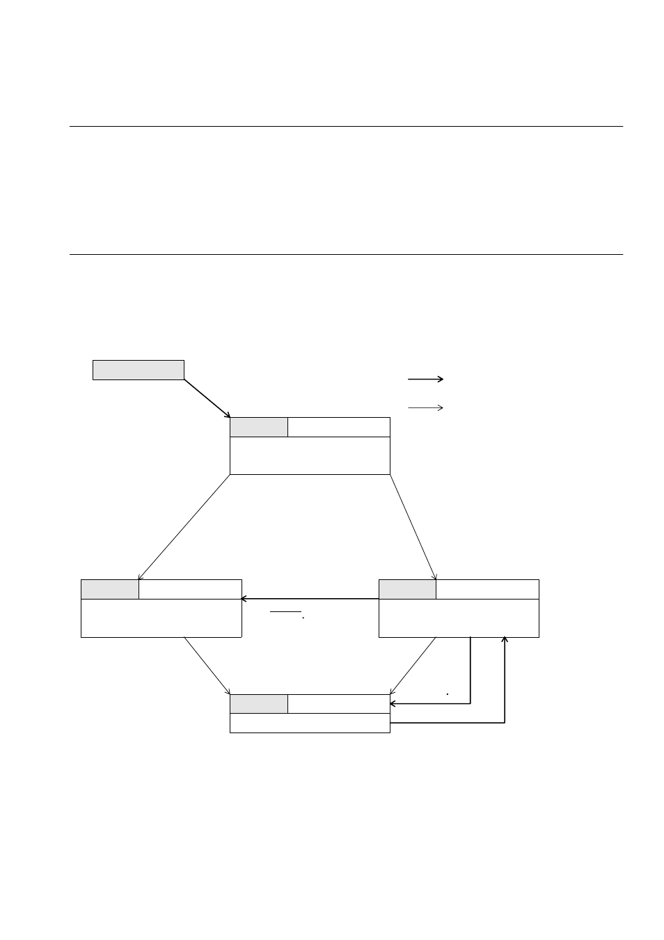
The states of the counter are determined by the CNTE bit of the control register and
the internal Wait signal as follows:
CNTE = "0", Wait = "1": Stop state
CNTE = "1", Wait = "1": Wait state (start trigger wait state)
CNTE = "1", Wait = "0": Run state
Figure 12.5-1 is a state transition diagram.
■
Counter States
Figure 12.5-1 Counter States Transition
C N T E = 0 , W A I T = 1
C N T E = ' 0 '
'
C N T E = ' 0 '
C N T E = ' 1 '
C N T E = ' 1 '
T R G = ' 0 '
T R G = ' 1 '
C N T E = 1 , W A I T = 1
C N T E = 1 , W A I T = 0
R E L D
T R G = ' 1 '
T R G = ' 1 '
R E L D U F
C N T E = 1 , W A I T = 0
S T O P
R E S E T
W A I T
U F
L O A D
R U N
State transition by hardware
State transition by register access
Counter: Operates
The contents of the reload register
are loaded to the counter.
Loading is completed.
Counter: Holds the value at a stop.
Immediately after resetting, this value
is undefined.
Counter: Holds the value at a stop.
The value is undefined immediately
after resetting until loading.