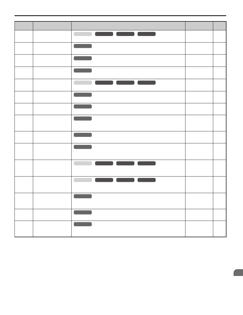
B parameter table – Yaskawa L1000E AC Drive CIMR-LEA User Manual
Page 211

B Parameter Table
YASKAWA TOEPYAIL1E01A YASKAWA AC Drive L1000E Quick Start Guide
211
Pa
ra
me
te
r T
abl
e
B
U2-06
(85H)
Motor Speed at Previous
Fault
Displays the motor speed at the previous fault.
No signal output
available
0.01%
U2-07
(86H)
Output Voltage at
Previous Fault
Displays the output voltage at the previous fault.
No signal output
available
0.1 Vac
U2-08
(87H)
DC Bus Voltage at
Previous Fault
Displays the DC bus voltage at the previous fault.
No signal output
available
1 Vdc
U2-09
(88H)
Output Power at Previous
Fault
Displays the output power at the previous fault.
No signal output
available
0.1 kW
U2-10
(89H)
Torque Reference at
Previous Fault
Displays the torque reference at the previous fault.
No signal output
available
0.1%
U2-11
(8AH)
Input Terminal Status at
Previous Fault
Displays the input terminal status at the previous fault. Displayed as in U1-10.
No signal output
available
–
U2-12
(8BH)
Output Terminal Status at
Previous Fault
Displays the output status at the previous fault. Displayed as in U1-11.
No signal output
available
–
U2-13
(8CH)
Drive Operation Status at
Previous Fault
Displays the operation status of the drive at the previous fault. Displayed as in
U1-12.
No signal output
available
–
U2-14
(8DH)
Cumulative Operation
Time at Previous Fault
Displays the cumulative operation time at the previous fault.
No signal output
available
1 h
U2-15
(7E0H)
Soft Starter Output at
Previous Fault
Displays the run speed after a soft start when a previous fault occurred.
Displayed as in U1-16.
No signal output
available
0.01%
U2-16
(7E1H)
Motor q-Axis Current at
Previous Fault
Displays the q-axis current for the motor at the previous fault. Displayed as in
U6-01.
No signal output
available
0.1%
U2-17
(7E2H)
Motor d-Axis Current at
Previous Fault
Displays the d-axis current for the motor at the previous fault. Displayed as in
U6-02.
No signal output
available
0.1%
U2-20
(8EH)
Heatsink Temperature at
Previous Fault
Displays the temperature of the heatsink when the most recent fault occurred.
Displayed as in U4-08.
No signal output
available
1
°C
U2-21
(7E6H)
Peak Hold Current
during Fault
Displays the peak current that occurred just prior to the previous fault.
No signal output
available
0.01 A
U2-22
(7E7H)
Peak Hold Frequency
during Fault
Displays the output frequency when the peak current displayed in U2-21
occurred.
No signal output
available
0.01 Hz
<10> The display resolution depends on the rated output power of the drive. Models 2A0018 to 2A0041 and 4A0009 to 4A0023 display values in
0.01 A units, while models 2A0059 to 2A0432 and 4A0030 to 4A0260 display values in 0.1 A units.
<31> Setting units are determined by the digital operator display unit selection (o1-03). When o1-03 = 0, the value is set in Hertz. When o1-03 = 4 or
5, the value is displayed in m/s. When o1-03 = 6, the value is displayed in ft/min.
<40> When checking the values of U1-03, U2-05 and U4-13 with the digital operator they are displayed in units of amperes, but when they are
checked using MEMOBUS communications, the monitor value in MEMOBUS communications is: displayed numeric value / 8192
× drive’s
rated current (A), from the condition “8192 (maximum value) = drive’s rated current (A)”.
No.
(Addr.)
Name
Description
Analog Output
Level
Unit
common
_
CLV
CLV/PM
V/f
OLV
All Modes
common
_
All Modes
common
_
All Modes
common
_
common
_
CLV
CLV/PM
V/f
OLV
All Modes
common
_
All Modes
common
_
All Modes
common
_
All Modes
common
_
All Modes
common
_
common
_
CLV
CLV/PM
V/f
OLV
common
_
CLV
CLV/PM
V/f
OLV
All Modes
common
_
All Modes
common
_
All Modes
common
_
