Yaskawa L1000E AC Drive CIMR-LEA User Manual
Page 127

4 Start-Up Programming
YASKAWA TOEPYAIL1E01A YASKAWA AC Drive L1000E Quick Start Guide
127
St
ar
t-
Up
Pr
og
ra
m
m
in
g
4
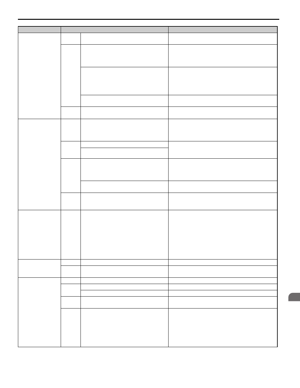
Jerk occurs due to
overshoot when the
motor reaches top
speed.
OLV
Too fast torque or slip compensation.
• Increase the Torque Compensation Delay Time (C4-02).
• Increase the Slip Compensation Delay Time (C3-02).
CLV
CLV/PM
Speed control loop setting is too soft or too hard.
• Adjust the Speed Control Loop Gain C5-01 and Integral
Time C5-02.
• Adjust Inertia Compensation parameters (n5-
) if speed
control loop settings can not solve the problem
Incorrect motor data.
• For induction motors readjust the motor data (E2-
),
especially the slip (E2-02) and no-load current values (E2-
03), or perform Auto-Tuning again.
• For PM motors readjust the motor data in E5-
or
perform Auto-Tuning.
Inertia compensation function is not set up
correctly.
If the Inertia Compensation Function is used (n5-01=1)
make sure the values in n5-02 and n5-03 are correct.
All
The acceleration rate changes too quickly when
reaching the selected speed.
Decrease the Jerk at the End of Acceleration. Decrease C2-
02 if set in m/s
2
, increase C2-02 if set in s.
Motor stops shortly
(undershoot) when the
leveling speed is
reached.
V/f and
OLV
Not enough torque at low speed.
Increase the Minimum and Middle Voltage Levels for the V/
f pattern voltage (E1-10 and E1-08 respectively). Make sure
that the Starting and Leveling
Current does not rise too high.
OLV and
CLV
Motor data incorrect.
Adjust the motor data (E2-
), especially the motor slip
(E2-02) and no-load current values (E2-03), or perform
Auto-Tuning.
Too much slip compensation.
CLV
CLV/PM
Speed control loop responds too slow.
Increase the Speed Control Gain and reduce the Speed
Control Integral Time used for Low Speed at Stop. The
parameters to be changed depend on the setting of C5-05
and whether a third set of speed loop settings is used.
The inertia compensation function is not set up
correctly.
If the Inertia Compensation Function is used (n5-01 = 1)
make sure the values in n5-02 and n5-03 are correct.
All
The deceleration rate changes too quickly when
reaching
leveling speed.
Decrease the Jerk at the End of Deceleration. Decrease C2-
04 if set in m/s
2
, increase C2-04 if set in s.
Motor speed
overshoot at
acceleration end and
undershoot when
reaching leveling
speed occurs. Problem
can not be resolved by
adjusting the speed
loop.
CLV
CLV/PM
Inertia is high.
Use the Inertia Compensation Function. Set n5-01 to 1 and
then adjust parameters n5-02 and n5-03.
Motor or machine
vibrates at high speed
or top speed.
OLV
Torque compensation responds too quickly.
Increase the Torque Compensation Delay Time (C4-02).
CLV
CLV/PM
Speed control loop adjusted too hard.
Decrease C5-01, then increase C5-02.
Motor or machine
vibrates in the low or
medium speed range.
V/f
Output voltage is too high.
Reduce the V/f Pattern settings (E1-08, E1-10).
OLV
Torque compensation is responding too quickly. Increase the Torque Compensation Delay Time (C4-02).
Output voltage is too high.
Reduce the V/f Pattern settings (E1-08, E1-10).
OLV
CLV
The value for the motor slip is set incorrectly.
Check the Motor Slip value in parameter E2-02. Increase or
decrease it in steps of 0.2 Hz.
CLV
CLV/PM
Speed control loop adjusted with too much gain.
• Decrease C5-01 and then increase C5-02 if the problem
occurs at speed higher than C5-07.
• Decrease C5-03 and then increase C5-04 if the problem
occurs at speed lower than C5-07.
• Decrease C5-13 and then increase C5-14 if the problem
occurs at speed lower than C5-07 but only during
deceleration.
Problem
Control Mode and Possible Cause
Corrective Action
