Yaskawa L1000E AC Drive CIMR-LEA User Manual
Page 135

5 Troubleshooting
YASKAWA TOEPYAIL1E01A YASKAWA AC Drive L1000E Quick Start Guide
135
Tr
ou
blesh
oot
ing
5
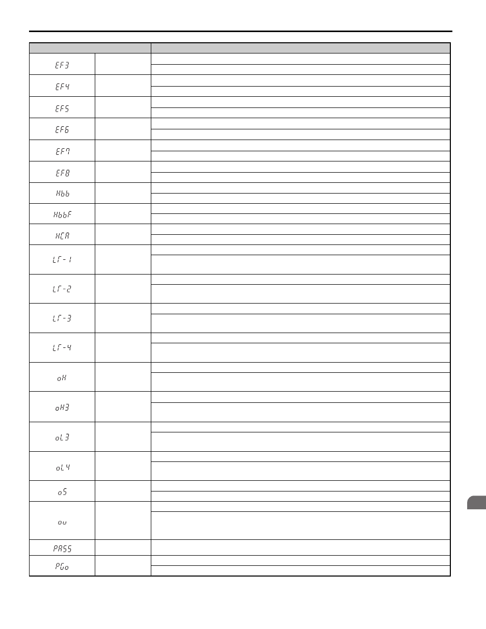
EF3
External fault (input terminal S3)
External fault at multi-function input terminal S3.
EF4
External fault (input terminal S4)
External fault at multi-function input terminal S4.
EF5
External fault (input terminal S5)
External fault at multi-function input terminal S5.
EF6
External fault (input terminal S6)
External fault at multi-function input terminal S6.
EF7
External fault (input terminal S7)
External fault at multi-function input terminal S7.
EF8
External fault (input terminal S8)
External fault at multi-function input terminal S8.
Hbb
Safe Disable Circuit Fault Signal (H1-HC, H2-HC) Release
Both Safe Disable Input channels are open.
HbbF
Safe Disable Circuit Fault Signal (H1-HC, H2-HC) Release
One Safe Disable channel is open while the other one is closed.
HCA
High Current Alarm
Drive current exceeded overcurrent warning level (150% of the rated current).
LT-1
Cooling Fan Maintenance Time
The cooling fan has reached its expected maintenance period and may need to be replaced.
Note: An alarm output (H2-
= 10) will only be triggered if H2-
= 2F.
LT-2
Capacitor Maintenance Time
The main circuit and control circuit capacitors are nearing the end of their expected performance life.
Note: An alarm output (H2-
= 10) will only be triggered if H2-
= 2F.
LT-3
Soft Charge Bypass Relay Maintenance Time
The DC bus soft charge relay is nearing the end of its expected performance life.
Note: An alarm output (H2-
= 10) will only be triggered if H2-
= 2F.
LT-4
IGBT Maintenance Time (90%)
IGBTs have reached 90% of their expected performance life.
Note: An alarm output (H2-
= 10) will only be triggered if H2-
= 2F.
oH
Heatsink Overheat
The temperature of the heatsink exceeded the overheat pre-alarm level set to L8-02 (90-100
°C). Default
value for L8-02 is determined by drive capacity (o2-04).
oH3
Motor Overheat Alarm (PTC thermistor input)
• The motor overheat signal to analog input terminal A1 or A2 exceeded the alarm detection level.
• Detection requires multi-function analog input H3-02 or H3-10 be set to “E”.
oL3
Overtorque Detection 1
Drive output current (or torque in OLV, CLV, CLV/PM) was greater than L6-02 for longer than the time
set in L6-03.
oL4
Overtorque Detection 2
Drive output current (or torque in OLV, CLV, CLV/PM) was greater than L6-05 for longer than the time
set in L6-06.
oS
Overspeed (for Control Mode with Encoder)
The motor speed feedback exceeded the F1-08 setting.
ov
DC Bus Overvoltage
The DC bus voltage exceeded the trip point.
For 200 V class: approximately 410 V
For 400 V class: approximately 820 V
PASS
MEMOBUS/Modbus Communication Test Mode Complete
PGo
Encoder Disconnected (for Control Mode with Encoder)
Detected when no encoder signal is received for a time longer than setting in F1-14.
Digital Operator Display
Minor Fault Name
