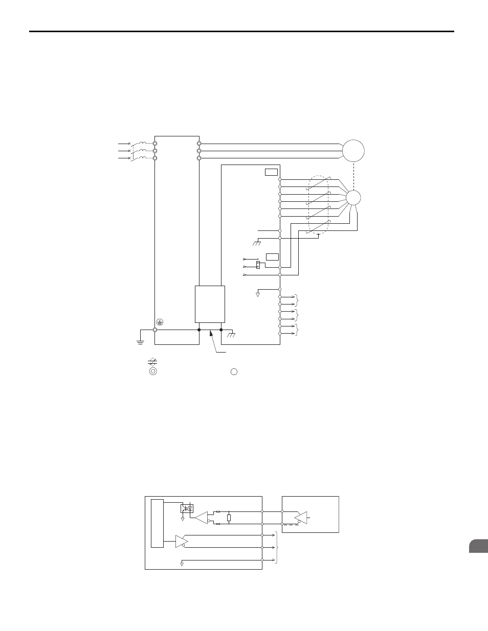
Figure 97, 7 option card installation, Connection diagram of pg-x3 – Yaskawa L1000E AC Drive CIMR-LEA User Manual
Page 155: Interface circuit

7 Option Card Installation
YASKAWA TOEPYAIL1E01A YASKAWA AC Drive L1000E Quick Start Guide
155
Op
tion
Ca
rd
In
st
al
lat
io
n
7
Connection Diagram of PG-X3
for a detailed description of the option board terminal functions.
The positioning of jumper CN3 selects the PG encoder power supply voltage (5.5 V or 12 V). Select the voltage level for
the PG encoder connected to the option and motor. If the wrong voltage is selected, the PG encoder may not operate
properly or may become damaged as a result.
Setting the PG Encoder Power Supply Voltage on page 156
for details.
Figure 97 PG-X3 Option and PG Encoder Connection Diagram
Note: The PG-X3 Option reads a maximum input frequency from the PG of 300 kHz. Be sure to select a PG with an output pulse
frequency of maximum 300 kHz when operating at maximum speed.
Take the following steps to prevent erroneous operation caused by noise interference:
• Use shielded wire for the PG encoder signal lines.
• Use separate conduit or cable tray dividers to separate option control wiring, main circuit input power wiring, and
motor output power cables.
Interface Circuit
Figure 89
Figure 98 Interface Circuit (PG-X3)
<1> Ground the shield on the PG side and the drive side. If noise problems arise in the PG signal, remove the shield ground from one end of the
signal line or remove the shield ground connection on both ends.
U/T1
V/T2
W/T3
R/L1
S/L2
T/L3
A+
A
B
Z
B+
Z+
a+
a
b
z
b+
z+
FE
IP
IG
IP12
IP5
IG
TB1
SG
SD
TB2
PG
NC
CN5-B
or
CN5-C
A
pulse
monitor signal
Ground wire
B
pulse
monitor signal
Z pulse monitor signal
YASKAWA
Drive
PG
X3
Option
CN3
M
FE
twisted-pair shielded line
main circuit terminal
control circuit terminal
X3
26LS32 level
26LS31
level
PG
X3
PG Encoder
A
,B,Z
A+,B+,Z+
600
Ω
a
,b,z
a+,b+,z+
SG
Monitor Signals
A,B,Z
A,B,Z
26LS31 level
