E: motor parameters, B parameter table – Yaskawa L1000E AC Drive CIMR-LEA User Manual
Page 172

B Parameter Table
172
YASKAWA TOEPYAIL1E01A YASKAWA AC Drive L1000E Quick Start Guide
d6: Field Forcing
■
E: Motor Parameters
E1: V/f Pattern
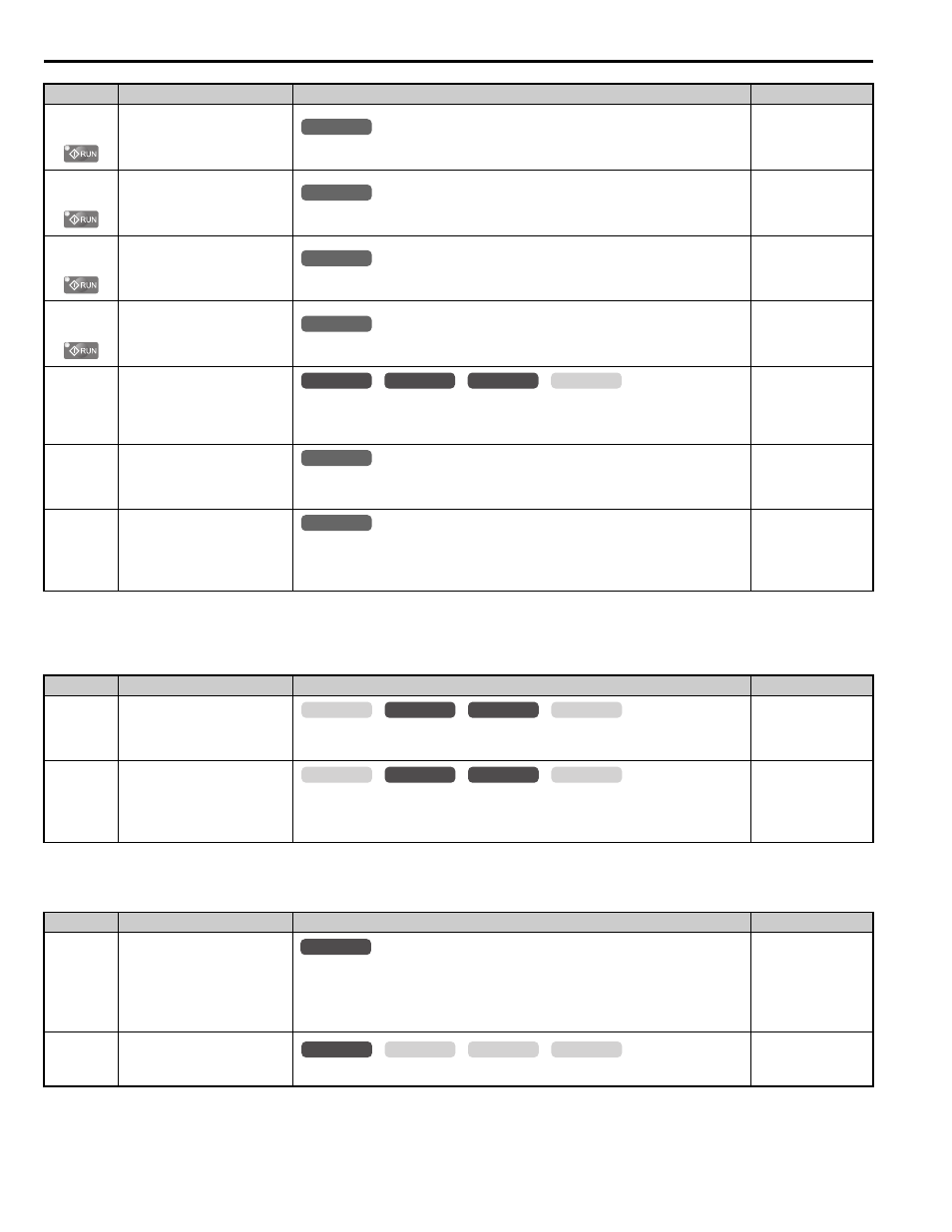
d1-23
(2C5H)
Releveling Speed
Sets speed reference for releveling when d1-18 = 1 or 2.
Default: 0.00%
Min: 0.00%
Max: 100.00%
d1-24
(2C6H)
Inspection Operation Speed
Sets speed reference when inspection operation is enabled.
Default: 50.00%
Min: 0.00%
Max: 100.00%
d1-25
(2C7H)
Rescue Operation Speed
Sets the speed reference during inspection operation.
Default: 10.00%
Min: 0.00%
Max: 100.00%
d1-26
(2C8H)
Leveling Speed
Sets leveling speed reference when d1-18 = 1 or 2.
Default: 8.00%
Min: 0.00%
Max: 100.00%
d1-27
(2C9H)
Motor 2 Speed Reference
Sets the speed reference for motor 2.
Note:
1. If set to 0.00, the drive will control motor 1 instead.
2. When using motor 2, be sure that the accel/decel times are set in parameters C1-12 and C1-13.
Default: 0.00 Hz
Min: 0.00 Hz
Max: 200.00 Hz
d1-28
(2CAH)
Leveling Speed Detection
Level
Used when d1-18 = 0 or 3. If the speed reference selected is lower than d1-28,
then the drive uses the leveling speed as the speed reference.
Default: 0.0%
Min: 0.0%
Max: 100.0%
d1-29
(2CBH)
Inspection Speed Detection
Level
Used when d1-18 = 0 or 3. If the speed reference selected is higher than d1-28
but lower or equal to d1-29, then the drive uses inspection speed as the speed
reference.
Default: 0.0%
Min: 0.0%
Max: 100.0%
<6> Setting ranges and defaults vary by the setting units determined by parameter o1-03.
Refer to Defaults and Setting Ranges by Display Unit Selection (o1-03) on page 217
.
No.(Addr.)
Name
Description
Setting
d6-03
(2A2H)
Field Forcing Selection
0: Disabled
1: Enabled
Default: 0
Min: 0
Max: 1
d6-06
(2A5H)
Field Forcing Limit
Sets the upper limit of the excitation current command during magnetic field
forcing. A setting of 100% is equal to motor no-load current. Disabled only
during DC Injection Braking.
Default: 400%
Min: 100%
Max: 400%
No.(Addr.)
Name
Description
Setting
E1-01
(300H)
Input Voltage Setting
This parameter must be set to the power supply voltage.
WARNING! Electrical Shock Hazard. Drive input voltage (not motor voltage)
must be set in E1-01 for the protective features of the drive to function properly.
Failure to do so may result in equipment damage and/or death or personal injury.
Min: 155 V
Max: 255 V
E1-03
(302H)
V/f Pattern Selection
F: Custom V/f, E1-04 through E1-13 settings define the V/f pattern
Default: F
Min: –
Max: F
No.(Addr.)
Name
Description
Setting
All Modes
common
_
All Modes
common
_
All Modes
common
_
All Modes
common
_
CLV
CLV/PM
V/f
OLV
common
_
All Modes
common
_
All Modes
common
_
common
_
CLV
CLV/PM
V/f
OLV
common
_
CLV
CLV/PM
V/f
OLV
All Modes
common
_
common
_
CLV
CLV/PM
V/f
OLV
