B parameter table – Yaskawa L1000E AC Drive CIMR-LEA User Manual
Page 210

B Parameter Table
210
YASKAWA TOEPYAIL1E01A YASKAWA AC Drive L1000E Quick Start Guide
U2: Fault Trace
U1-16
(53H)
Output Speed after Soft
Start
Displays output speed with ramp time and jerk settings. Units determined by
o1-03.
10 V: Max
frequency
(-10 to +10 V)
0.01%
U1-17
(58H)
DI-A3 Option Card Input
Status
Displays the reference value input from the DI-A3 option card.
Display will appear in hexadecimal as determined by the digital card input
selection in F3-01.
3FFFF: Set (1 bit) + sign (1 bit) + 16 bit
No signal output
available
–
U1-18
(61H)
oPE Fault Parameter
Displays the parameter number that caused the oPE02 or oPE08 (Operation
error).
No signal output
available
–
U1-19
(66H)
MEMOBUS/Modbus
Error Code
Displays the contents of a MEMOBUS/Modbus error.
No signal output
available
–
U1-25
(4DH)
Software Number (Flash)
FLASH ID
No signal output
available
–
U1-26
(5BH)
Software No. (ROM)
ROM ID
No signal output
available
–
<9> Values shown here are for 200 V class drives. Double the value when using a 400 V class drive.
<10> The display resolution depends on the rated output power of the drive. Models 2A0018 to 2A0041 and 4A0009 to 4A0023 display values in
0.01 A units, while models 2A0059 to 2A0432 and 4A0030 to 4A0260 display values in 0.1 A units.
<12> The display resolution depends on the rated output power of the drive. Models 2A0018 to 2A0041 and 4A0009 to 4A0023 display values in
0.01 kW units, while models 2A0059 to 2A0432 and 4A0030 to 4A0260 display values in 0.1 kW units.
<31> Setting units are determined by the digital operator display unit selection (o1-03). When o1-03 = 0, the value is set in Hertz. When o1-03 = 4 or
5, the value is displayed in m/s. When o1-03 = 6, the value is displayed in ft/min.
<40> When checking the values of U1-03, U2-05 and U4-13 with the digital operator they are displayed in units of amperes, but when they are
checked using MEMOBUS communications, the monitor value in MEMOBUS communications is: displayed numeric value / 8192
× drive’s
rated current (A), from the condition “8192 (maximum value) = drive’s rated current (A)”.
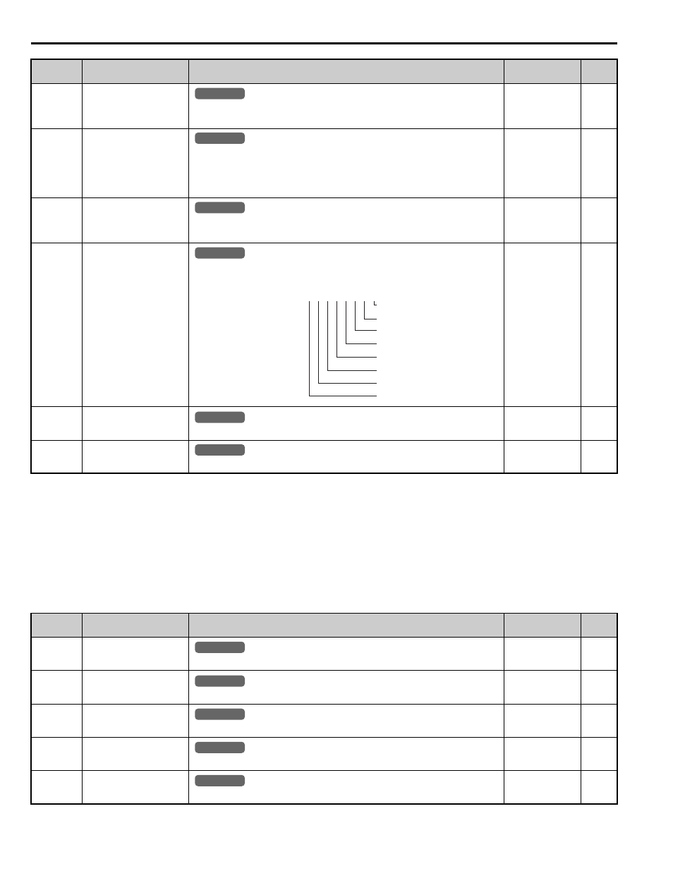
No.
(Addr.)
Name
Description
Analog Output
Level
Unit
U2-01
(80H)
Current Fault
Displays the current fault.
No signal output
available
–
U2-02
(81H)
Previous Fault
Displays the previous fault.
No signal output
available
–
U2-03
(82H)
Speed Reference at
Previous Fault
Displays the speed reference at the previous fault.
No signal output
available
0.01%
U2-04
(83H)
Output Speed at Previous
Fault
Displays the output speed at the previous fault.
No signal output
available
0.01%
U2-05
(84H)
Output Current at
Previous Fault
Displays the output current at the previous fault.
No signal output
available
No.
(Addr.)
Name
Description
Analog Output
Level
Unit
All Modes
common
_
All Modes
common
_
All Modes
common
_
All Modes
common
_
U1 - 19= 00000000
CRC Error
Data Length Error
Not Used
Parity Error
Overrun Error
Framing Error
Timed Out
Not Used
1
1
0
1
1
1
1
0
YEAco
mmon
All Modes
common
_
All Modes
common
_
All Modes
common
_
All Modes
common
_
All Modes
common
_
All Modes
common
_
All Modes
common
_
