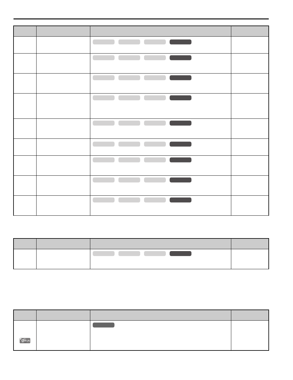
O: operator related parameters, B parameter table – Yaskawa L1000E AC Drive CIMR-LEA User Manual
Page 196

B Parameter Table
196
YASKAWA TOEPYAIL1E01A YASKAWA AC Drive L1000E Quick Start Guide
n9
:
Current Detection Adjustments
■
o: Operator Related Parameters
The o parameters set up the digital operator displays.
o1: Digital Operator Display Selection
n8-33
(560H)
d-Axis Current Control
Integral Time during Normal
Operation
Sets the d axis integral time for the normal control range.
Default: 10.0 ms
Min: 0.0 ms
Max: 100.0 ms
n8-35
(562H)
Initial Rotor Position
Detection Selection
1: High frequency injection
2: Pulse injection
Default: 1
Min: 1
Max: 2
n8-36
(563H)
High Frequency Injection
Level
Sets the frequency in Hz for the superimposed signal used for superimposed
harmonics.
Default: 500 Hz
Min: 25 Hz
Max: 1000 Hz
n8-37
(564H)
High Frequency Injection
Amplitude
Sets the amplitude for superimposed harmonics according to the voltage class of
the motor. Adjust this value when there is too much or too little current as a
result of the settings assigned to motor parameters.
Default: 20.0%
Min: 0.0%
Max: 99.9%
n8-62
(57DH)
Output Voltage Limit
Prevents output voltage saturation. Should be set just below the voltage provided
by the input power supply.
Default: 200.0 V
Min: 0.0 V
Max: 230.0 V
n8-81
(2D0H)
High Frequency Injection
during Rescue Operation
Sets the frequency used for Polar Detection Method 1 during Rescue Operation.
Default: 90 Hz
Min: 25 Hz
Max: 1000 Hz
n8-82
(2D1H)
High Frequency Injection
Amplitude during Rescue
Operation
Sets the amplitude for High Frequency Injection during Rescue Operation as a
percentage of the voltage (200 V or 400 V).
Default: 15.0%
Min: 0.1%
Max: 99.9%
n8-84
(2D3H)
Polarity Detection Current
Sets the current level (E5-03) as a percentage for detecting polarity during Initial
Polarity Estimation.
Default: 100%
Min: 0%
Max: 150%
n8-86
(2D5H)
Magnet Pole Search Error
Detection Selection
0: Disabled
1: Enabled
Default: 0
Min: 0
Max: 1
<9> Values shown here are for 200 V class drives. Double the value when using a 400 V class drive.
No.
(Addr.)
Name
Description
Setting
n9-60
(64DH)
<4> Default setting is determined by the drive model (o2-04).
A/D Conversion Start Delay
Sets a delay time for starting the current signal A/D conversion. This value
seldom needs to be changed.
Default:
Min: 0.0
μs
Max: 40.0
μs
No.
(Addr.)
Name
Description
Setting
o1-01
(500H)
Drive Mode Unit Monitor
Selection
Switches the display after the power has been turned on. When using an LED
operator, pressing the up arrow key will display the following data: frequency
reference
→ rotational direction → output frequency → output current → output
voltage
→ U1-
.
Default: 106
(Monitor U1-06)
Min: 105
Max: 699
No.
(Addr.)
Name
Description
Setting
common
_
CLV
CLV/PM
V/f
OLV
common
_
CLV
CLV/PM
V/f
OLV
common
_
CLV
CLV/PM
V/f
OLV
common
_
CLV
CLV/PM
V/f
OLV
common
_
CLV
CLV/PM
V/f
OLV
common
_
CLV
CLV/PM
V/f
OLV
common
_
CLV
CLV/PM
V/f
OLV
common
_
CLV
CLV/PM
V/f
OLV
common
_
CLV
CLV/PM
V/f
OLV
common
_
CLV
CLV/PM
V/f
OLV
All Modes
common
_
