9 click save, Routers – Grass Valley NV9000-SE v.3.0 User Manual
Page 89
NV9000-SE Utilities • User’s Guide
69
7. Routers
Adding a Router
8 In the right-hand area of the ‘Physical Levels’ section, enter options in the fields provided:
9 Click
Save
.
10 Click
X
on the window title tab to close the page.
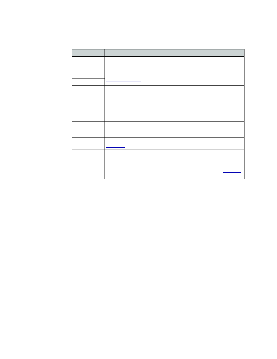
Field
Description
Input Protect
Protects and/or locks inputs or outputs. When locked it cannot be changed. When
protected, it can be changed, but only with proper authorization.
From the drop-down list, select ‘Disabled’ to remove protect or unlock, or ‘In
Server’ to enable protect or lock in the server. For more information, see
Input Lock
Output Protect
Output Lock
Shared Control
Informs the NV9000 system controller whether another control system is connected
to this physical level. From the drop-down list, select ‘True’ to verify that another
control system is connected to the router control card and that it can initiate
crosspoint changes. The NV9000 allows it and updates its tables periodically with
these changes. (Unexpected changes are not logged as errors.).
If ‘False’ is selected, the NV9000 manages this physical level exclusively, and does
not permit crosspoint changes that it does not initiate.
Signal Type
Distinguishes whether the router is used for switching signals or for machine
control. From the drop-down list, select ‘Machine Control’ for machine control or
‘XY or standard’ for signal switching.
Number Virtual
XPTS
Enter the number of virtual crosspoints. For more information, see
Chop Interval
Enter the number of frames for the chop interval. The default is 6 frames.
When supported by the router, ‘chop’ rapidly switches the selected destination
between its current source and the preset source.
Virtual XPT
Default Input
Enter the default input for virtual crosspoint. For more information, see