Tielines – Grass Valley NV9000-SE v.3.0 User Manual
Page 498
478
Rev 3.0 • 25 Mar 10
16. Tielines
Updating a Tieline
Or
Click anywhere in the row listing the tieline being viewed and click
Edit Selected Tieline
. Use
the ‘Shift’ or ‘Ctrl’ key on your keyboard to select multiple tielines. Each tieline opens in a sep-
arate tabbed window. Click the tab to bring the window forward.
4 If adding a device, select a new device(s) for the tieline configuration. Devices are listed in the
‘Phys Levels’ section:
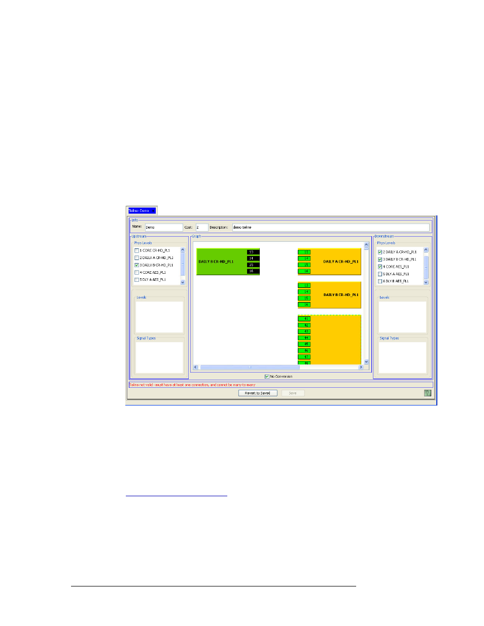
In the ‘Upstream’ section, check the check box next to the new source router, if needed. The
router displays as a green figure in the ‘Graph’ field, as shown in Figure 16-16. Only one
upstream device may be selected.
In the ‘Downstream’ section, check the check box next to the destination device, if needed.
Multiple destination devices may be selected. The device displays as an amber figure in the
‘Graph’ field:
Figure 16-16. Tieline Details Page, New Tieline
5 If removing a device, uncheck the check box in the ‘Phys Level’ section (either ‘Upstream’ or
‘Downstream’) that corresponds to the device you want to remove. The device disappears from
the ‘Graph’ section.
6 Depending on the devices that now display in the ‘Graph’ section, create connections as
needed.
Using your mouse pointer, draw an arrow from the downstream port to the upstream port. (See
Using the ‘Tieline Details’ Page
on page 460.) Multiple downstream ports may be mapped to
one upstream port, but multiple downstream ports cannot be mapped to multiple upstream ports
(and vice versa). If no ports are listed (e.g. numbered box), there are no ports available for the
tieline.
As each port is selected, you can click on the arrow to activate the ‘Virtual ‘Levels’ and ‘Signal
Types’ sections and view the corresponding virtual levels and signal types for that port.