Guralp Systems CMG-DCM build <10,000 User Manual
Page 85
Operator's Guide
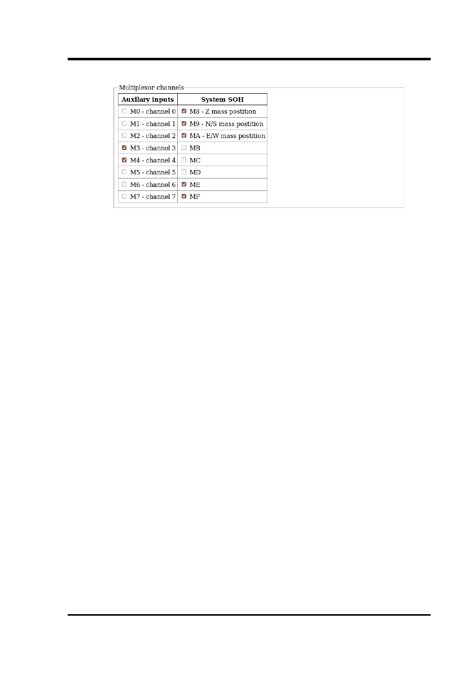
Inputs M3 through M7 and MB through MF are typically derived by
digitising (at 16-bit resolution) the analogue inputs on the “Auxiliary”
connector of the digitiser although, in some configurations, they may
be connected to internal sensors. M8, M9 and MA provide mass
position data from the first sensor and, for seven-channel digitisers,
M0, M1 and M2 perform the same function for the second instrument.
Output from each displayed channel can be enabled by ticking the
associated check-box or disabled by clearing it.
This is followed by the Transmission Mode selection dialogue (not
reproduced here). One mode can be selected from the following list:
•
Direct mode - Data are transmitted in real-time, without being
copied to local storage. Only a small transmit buffer is used.
•
Filing mode - Data are stored in local flash storage. A periodic
status heartbeat is transmitted to inform listeners that data
are available from storage.
•
Adaptive mode - Data are transmitted in real-time whenever
possible. Any unacknowledged transmission is stored, and
retransmitted oldest first when the line is not being used for
real-time traffic.
•
FIFO mode - Data are stored locally and transmitted in strict
FIFO order. If the link is lost for a period, real-time data will
be delayed while the stored data are transmitted.
•
Dual mode - Continuous data are transmitted as in "direct"
mode and Triggered data is stored in flash as in "filing" mode.
November 2010
85