Guralp Systems CMG-DCM build <10,000 User Manual
Page 194
CMG-EAM (Platinum Firmware)
In the example above, all channels are set to unity gain (channel 0 is
the vertical component and 1, 2 and 3 are the North/South, East/West
and auxiliary/calibration channels, respectively. On a seven-channel
digitiser, channels 4, 5 and 6 are the vertical, North/South and
East/West components for the second instrument). If variable-gain-
aware firmware (v106b42 and above) is loaded on a digitiser without
variable-gain hardware, the text “No gain stage” will appear in this
position in the boot status stream.
The selected gain setting is encoded into the GCF headers by
appropriating bits from the System ID which must, therefore, be
chosen to be five (or fewer) characters long. See the note at the end of
this section for more information. The InfoBlocks (see section 7 on
page78) should be changed to reflect the amended System ID but the
gain figure taken from the calibration document should be used
unchanged, regardless of the variable gain setting chosen. Similarly
the “calvals” file in Scream! should not be changed, other than to
reflect the System ID; Scream! can deduce the variable gain settings in
use from the GCF block headers and automatically take account of
these during calibration operations.
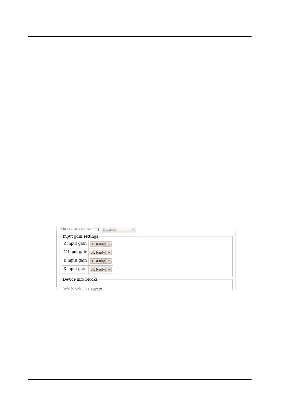
To change the gain using the web interface, select the digitiser from
the list in the “System setup” section of the “Configuration” menu and
scroll down to the “Connected devices” section. The following
additional sub-section appears:
(This table is extended to show three additional components when a
seven-channel digitiser is detected.)
From here, the gain can be set individually for each component. If the
“Submit” button is clicked, the changes will be stored in the digitiser
module's configuration but will not take effect until the module is
rebooted. If an immediate change is required, the “Submit & Reboot
digitiser” button should be used instead.
194
Issue C